Philips Semiconductors
Product specification
128 × 8-bit EEPROM with I2C-bus interface
PCA8581; PCA8581C
7.5
I2C-bus protocol
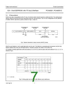
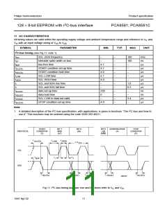
Before any data is transmitted on the I2C-bus, the device which should respond is addressed first. The addressing is
always carried out with the first byte transmitted after the start procedure. The I2C-bus configuration for the different
PCA8581 WRITE and READ cycles is shown in Figs 7, 9 and 10.
acknowledgement
from slave
acknowledgement
from slave
acknowledgement
from slave
handbook, full pagewidth
S
SLAVE ADDRESS
0
A
X
WORD ADDRESS
A
DATA
A
P
WRITING
t
don't
care
R/W
n bytes
WR
auto increment
memory word address
MLB889
Fig.7 Master transmits to slave receiver (WRITE) mode.
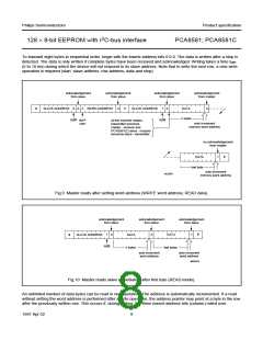
After the word address, one-to-eight data bytes can be sent. The address is automatically incremented, but the four
highest address bits (row) are internally latched. Therefore all bytes are written in the same row.
An example of writing eight bytes with word address X 0 0 0 0 0 0 0 and six bytes with word address X 0 0 1 0 1 0 1 is
shown in Fig.8.
handbook, full pagewidth
(1)
Word Address
Row
X0000000
X0001...
0
1
2
3
1
4
2
5
3
6
4
5
6
1
7
2
8
3
X0010101
X0011...
column
0
1
2
3
4
5
6
7
MLB890
(1) X = don’t care.
Fig.8 Writing eight and six bytes with different word addresses.
7
1997 Apr 02

 NXP [ NXP ]