Philips Semiconductors
Product specification
128 × 8-bit EEPROM with I2C-bus interface
PCA8581; PCA8581C
5
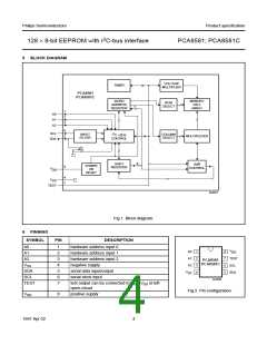
BLOCK DIAGRAM
handbook, full pagewidth
VOLTAGE
MULTIPLIER
TIMER
PCA8581
PCA8581C
WORD
ADDRESS
REGISTER
MEMORY
CELL
ARRAY
ROW
SELECT
7
1
2
3
A0
A1
A2
6
5
2
SCL
SDA
INPUT
FILTER
COLUMN
SELECT
I C BUS
MULTIPLEXER
CONTROL
8
SHIFT
REGISTER
R/W
CONTROL
POWER
ON
8
V
DD
RESET
4
7
V
SS
TEST
MLB887
Fig.1 Block diagram.
6
PINNING
SYMBOL
PIN
DESCRIPTION
A0
1
2
3
4
5
6
7
hardware address input 0
hardware address input 1
hardware address input 2
negative supply
fpage
V
A0
A1
A2
1
2
3
4
8
7
6
5
DD
A1
TEST
SCL
A2
PCA8581
PCA8581C
VSS
SDA
SCL
TEST
serial data input/output
serial clock input
V
SDA
SS
MLB888
test output can be connected to VSS, VDD or left
open-circuit
Fig.2 Pin configuration.
VDD
8
positive supply
1997 Apr 02
4

 NXP [ NXP ]