Philips Semiconductors
Product specification
128 × 8-bit EEPROM with I2C-bus interface
PCA8581; PCA8581C
11 AC CHARACTERISTICS
All timing values are valid within the operating supply voltage and ambient temperature range and reference to VIL and
VIH with an input voltage swing of VSS to VDD
.
SYMBOL
PARAMETER
MIN.
TYP.
MAX.
UNIT
I2C-bus timing (see Fig.11; note 1)
fSCL
SCL clock frequency
−
−
−
−
−
−
−
−
−
−
−
−
−
−
−
100
kHz
tSP
tolerable spike width on bus
bus free time
100
−
ns
µs
µs
µs
µs
µs
µs
µs
ns
ns
µs
µs
tBUF
4.7
4.7
4.0
4.7
4.0
−
tSU;STA
tHD;STA
tLOW
tHIGH
tr
START condition set-up time
START condition hold time
SCL LOW time
−
−
−
SCL HIGH time
−
SCL and SDA rise time
SCL and SDA fall time
data set-up time
1.0
0.3
−
tf
−
tSU;DAT
tHD;DAT
tVD;DAT
tSU;STO
250
0
data hold time
−
SCL LOW to data out valid
STOP condition set-up time
−
3.4
−
4.0
Note
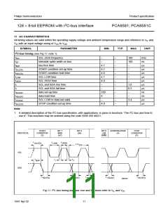
1. A detailed description of the I2C-bus specification, with applications, is given in brochure “The I2C-bus and how to
use it”. This brochure may be ordered using the code 9398 393 40011.
handbook, full pagewidth
START
CONDITION
(S)
BIT 7
MSB
(A7)
BIT 6
(A6)
BIT 0
LSB
(R/W)
ACKNOWLEDGE
(A)
STOP
CONDITION
(P)
PROTOCOL
t
t
t
HIGH
SU;STA
LOW
1 / f
SCL
SCL
SDA
t
t
t
f
BUF
r
t
t
t
t
t
HD;STA
SU;DAT
VD;DAT
SU;STO
HD;DAT
MBD820
Fig.11 I2C-bus timing diagram; rise and fall times refer to VIL and VIH.
1997 Apr 02
11

 NXP [ NXP ]