Philips Semiconductors
Preliminary specification
80C51 8-bit microcontroller
8K/256 OTP, 8 channel 10 bit A/D, I2C, PWM,
capture/compare, high I/O, low voltage (2.7V–5.5V), low power
P87C552
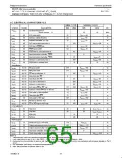
AC ELECTRICAL CHARACTERISTICS
16MHz CLOCK
VARIABLE CLOCK
MIN MAX
SYMBOL
1/t
FIGURE
PARAMETER
MIN
MAX
UNIT
5
48
Oscillator frequency
CLCL
Speed version : S
3.5
16
MHz
ns
ns
ns
ns
ns
ns
ns
ns
ns
ns
ns
t
t
t
t
t
t
t
t
t
t
t
48
48
48
48
48
48
48
48
48
48
48
ALE pulse width
85
22
32
2t
–40
LHLL
CLCL
Address valid to ALE low
Address hold after ALE low
ALE low to valid instruction in
ALE low to PSEN low
t
–40
–30
AVLL
LLAX
LLIV
CLCL
CLCL
t
150
82
4t
3t
–100
CLCL
32
t
–30
LLPL
PLPH
PLIV
PXIX
PXIZ
CLCL
PSEN pulse width
142
3t
–45
CLCL
PSEN low to valid instruction in
Input instruction hold after PSEN
Input instruction float after PSEN
Address to valid instruction in
PSEN low to address float
–105
CLCL
0
0
37
207
10
t
–25
CLCL
5
5t
–105
AVIV
CLCL
10
PLAZ
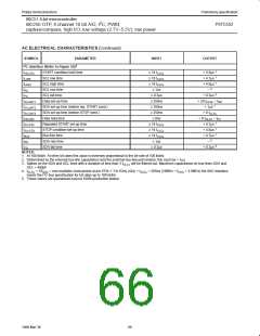
Data Memory
t
t
t
t
t
t
t
t
t
t
t
t
t
t
49, 50
49, 50
49, 50
49, 50
49, 50
49, 50
49, 50
49, 50
49, 50
49, 50
49, 50
50
RD pulse width
275
275
6t
–100
–100
ns
ns
ns
ns
ns
ns
ns
ns
ns
ns
ns
ns
ns
ns
RLRH
WLWH
RLDV
RHDX
RHDZ
LLDV
CLCL
WR pulse width
6t
CLCL
RD low to valid data in
Data hold after RD
147
5t
–165
CLCL
0
0
Data float after RD
65
2t
–60
CLCL
ALE low to valid data in
Address to valid data in
ALE low to RD or WR low
Address valid to WR low or RD low
Data valid to WR transition
Data hold after WR
350
397
239
8t
CLCL
9t
CLCL
–150
–165
AVDV
LLWL
137
122
13
3t
–50
3t
+50
CLCL
CLCL
4t
t
–130
–50
AVWL
QVWX
WHQX
QVWH
RLAZ
WHLH
CLCL
CLCL
CLCL
CLCL
13
t
–50
Data valid to WR high
RD low to address float
RD or WR high to ALE high
287
7t
–150
49, 50
49, 50
0
0
23
103
t
–40
t
+40
CLCL
CLCL
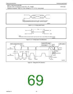
External Clock
t
t
t
t
51
51
51
51
High time
Low time
Rise time
Fall time
20
20
20
20
t
–t
ns
ns
ns
ns
CHCX
CLCX
CLCH
CHCL
CLCL CLCX
t
–t
CLCL CHCX
20
20
20
20
Shift Register
t
t
t
t
t
52
52
52
52
52
Serial port clock cycle time
750
492
8
12t
ns
ns
ns
ns
ns
XLXL
CLCL
Output data setup to clock rising edge
Output data hold after clock rising edge
Input data hold after clock rising edge
Clock rising edge to input data valid
10t
–133
QVXH
XHQX
XHDX
XHDV
CLCL
2t
CLCL
–117
0
0
492
10t
–133
CLCL
NOTES:
1. Parameters are valid over operating temperature range unless otherwise specified.
2. Load capacitance for port 0, ALE, and PSEN = 100pF, load capacitance for all other outputs = 80pF.
3. Interfacing the microcontroller to devices with float times up to 45ns is permitted. This limited bus contention will not cause damage to Port 0
drivers.
4. See application note AN457 for external memory interface.
5. Parts are guaranteed to operate down to 0Hz.
65
1999 Mar 30

 NXP [ NXP ]