Philips Semiconductors
Product specification
CAN controller interface
PCA82C250
LIMITING VALUES
In accordance with the Absolute Maximum Rating System (IEC 60134); all voltages are referenced to pin 2;
positive input current.
SYMBOL
VCC
PARAMETER
supply voltage
CONDITIONS
MIN.
−0.3
MAX.
+9.0
UNIT
V
V
V
Vn
DC voltage at pins 1, 4, 5 and 8
DC voltage at pins 6 and 7
−0.3
−8.0
VCC + 0.3
+18.0
V6, 7
0 V < VCC < 5.5 V;
no time limit
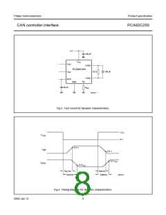
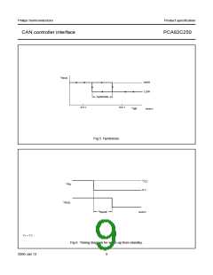
Vtrt
transient voltage at pins 6 and 7
storage temperature
see Fig.8
−150
−55
+100
+150
+125
+150
+2000
+200
V
Tstg
Tamb
Tvj
°C
°C
°C
V
ambient temperature
−40
virtual junction temperature
electrostatic discharge voltage
note 1
note 2
note 3
−40
Vesd
−2000
−200
V
Notes
1. In accordance with “IEC 60747-1”. An alternative definition of virtual junction temperature is:
Tvj = Tamb + Pd × Rth(vj-a), where Rth(j-a) is a fixed value to be used for the calculation of Tvj. The rating for Tvj limits
the allowable combinations of power dissipation (Pd) and ambient temperature (Tamb).
2. Classification A: human body model; C = 100 pF; R = 1500 Ω; V = ±2000 V.
3. Classification B: machine model; C = 200 pF; R = 25 Ω; V = ±200 V.
THERMAL CHARACTERISTICS
SYMBOL
Rth(j-a)
PARAMETER
CONDITIONS
in free air
VALUE
UNIT
thermal resistance from junction to ambient
PCA82C250
100
160
K/W
K/W
PCA82C250T
QUALITY SPECIFICATION
According to “SNW-FQ-611 part E”.
2000 Jan 13
5

 NXP [ NXP ]