Philips Semiconductors
Preliminary specification
2-input EXCLUSIVE-OR gate
74LVC1G86
V
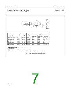
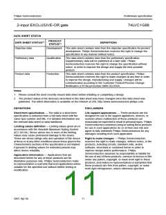
handbook, full pagewidth
EXT
V
CC
R
L
V
V
O
I
PULSE
GENERATOR
D.U.T.
C
R
R
L
L
T
MNA616
VEXT
tPLH/tPHL tPZH/tPHZ tPZL/tPLZ
VCC
VI
VCC
CL
RL
1.65 to 1.95 V
2.3 to 2.7 V
2.7 V
30 pF
30 pF
50 pF
50 pF
50 pF
1 kΩ
open
GND
GND
GND
GND
GND
2 × VCC
2 × VCC
6 V
VCC
500 Ω
500 Ω
500 Ω
500 Ω
open
open
open
open
2.7 V
2.7 V
VCC
3.0 to 3.6 V
4.5 to 5.5 V
6 V
2 × VCC
Definitions for test circuit:
RL = Load resistor.
CL = Load capacitance including jig and probe capacitance.
RT = Termination resistance should be equal to the output impedance Zo of the pulse generator.
Fig.6 Load circuitry for switching times.
2001 Apr 06
7

 NXP [ NXP ]