Philips Semiconductors
Product specification
8-channel analog multiplexer/demultiplexer
74HC/HCT4051
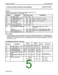
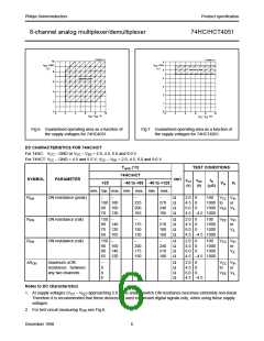
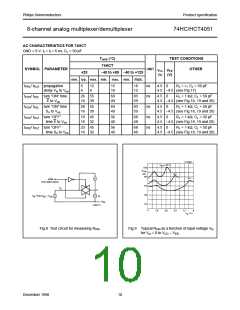
Fig.6 Guaranteed operating area as a function of
the supply voltages for 74HC4051.
Fig.7 Guaranteed operating area as a function of
the supply voltages for 74HCT4051.
DC CHARACTERISTICS FOR 74HC/HCT
For 74HC: VCC − GND or VCC − VEE = 2.0, 4.5, 6.0 and 9.0 V
For 74HCT: VCC − GND = 4.5 and 5.5 V; VCC − VEE = 2.0, 4.5, 6.0 and 9.0 V
Tamb (°C)
TEST CONDITIONS
74HC/HCT
SYMBOL
PARAMETER
UNIT
VCC VEE
IS
(µA)
+25
−40 to +85 −40 to +125
Vis VI
(V)
(V)
min. typ. max. min. max. min. max.
RON
ON resistance (peak)
−
−
−
−
Ω
Ω
Ω
Ω
2.0
4.5
6.0
0
0
0
100
VCC VIH
100 180
90 160
70 130
225
200
165
270
240
195
1000 to
1000 VEE VIL
or
4.5 −4.5 1000
RON
ON resistance (rail)
ON resistance (rail)
150
−
−
−
Ω
Ω
Ω
Ω
2.0
4.5
6.0
0
0
0
100
1000
1000
VEE VIH
80 140
70 120
60 105
175
150
130
210
180
160
or
VIL
4.5 −4.5 1000
RON
150
−
−
−
Ω
Ω
Ω
Ω
2.0
4.5
6.0
0
0
0
100
1000
1000
VCC VIH
90 160
80 140
65 120
200
175
150
240
210
180
or
VIL
4.5 −4.5 1000
∆RON
maximum ∆ON
resistance between
any two channels
−
9
8
6
Ω
Ω
Ω
Ω
2.0
4.5
6.0
0
0
0
VCC VIH
to
or
VEE VIL
4.5 −4.5
Notes to DC characteristics
1. At supply voltages (VCC − VEE) approaching 2.0 V the analog switch ON-resistance becomes extremely non-linear.
Therefore it is recommended that these devices be used to transmit digital signals only, when using these supply
voltages.
2. For test circuit measuring RON see Fig.8.
December 1990
6

 NXP [ NXP ]