Philips Semiconductors
Product specification
8-channel analog multiplexer/demultiplexer
74HC/HCT4051
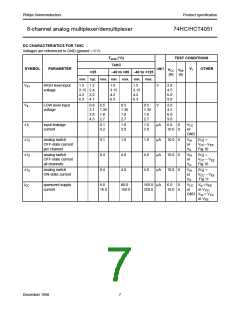
DC CHARACTERISTICS FOR 74HCT
Voltages are referenced to GND (ground = 0)
Tamb (°C)
TEST CONDITIONS
74HCT
SYMBOL PARAMETER
UNIT
VCC VEE
+25
−40 to +85
−40 to +125
Vi
OTHER
(V)
(V)
min. typ. max. min.
max.
min.
max.
VIH
VIL
± II
± IS
HIGH level
input voltage
2.0
1.6
2.0
2.0
V
4.5
to
5.5
LOW level
input voltage
1.2 0.8
0.1
0.8
0.8
1.0
1.0
V
4.5
to
5.5
input leakage
current
1.0
1.0
µA
µA
5.5
0
VCC
or
GND
analog switch
OFF-state
current per
channel
0.1
10.0 0
10.0 0
10.0 0
VIH
or
VIL
|VS| =
CC − VEE
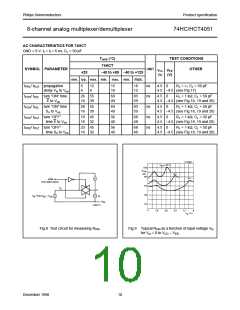
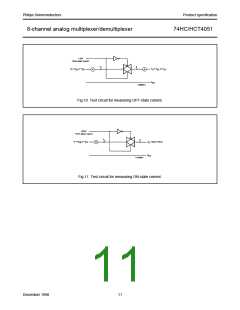
(see Fig.10)
V
± IS
analog switch
OFF-state
current all
channels
0.4
4.0
4.0
4.0
4.0
µA
µA
VIH
or
VIL
|VS| =
V
CC −VEE
(see Fig.10)
± IS
analog switch
ON-state
current
0.4
8.0
VIH
or
VIL
|VS| =
V
CC−VEE
(see Fig.11)
ICC
quiescent
supply current
80.0
160.0
160.0 µA
5.5
0
VCC Vis =VEE or
VCC
16.0
320.0
5.0 −5.0 or
;
GND Vos = VCC
or VEE
∆ICC
additional
quiescent
100 360
450
490
µA
4.5
to
0
VCC other inputs
− 2.1 at VCC or
supply current
per input pin
for unit load
coefficient is 1
(note 1)
5.5
V
GND
Note to HCT types
1. The value of additional quiescent supply current (∆ ICC) for a unit load of 1 is given here.
To determine ∆ICC per input, multiply this value by the unit load coefficient shown in the table below.
INPUT
UNIT LOAD COEFFICIENT
Sn
E
0.50
0.50
December 1990
9

 NXP [ NXP ]