Philips Semiconductors
Product specification
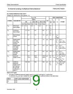
8-channel analog multiplexer/demultiplexer
74HC/HCT4051
RATINGS
Limiting values in accordance with the Absolute Maximum System (IEC 134)
Voltages are referenced to VEE = GND (ground = 0 V)
SYMBOL
VCC
PARAMETER
DC supply voltage
MIN. MAX. UNIT
CONDITIONS
−0.5 +11.0 V
±IIK
±ISK
±IS
DC digital input diode current
DC switch diode current
DC switch current
20
20
25
20
50
mA
mA
mA
mA
mA
for VI < −0.5 V or VI > VCC + 0.5 V
for VS < −0.5 V or VS > VCC + 0.5 V
for −0.5 V < VS < VCC + 0.5 V
±IEE
DC VEE current
±ICC; ±IGND DC VCC or GND current
Tstg
Ptot
storage temperature range
−65
+150 °C
power dissipation per package
for temperature range: −40 to +125 °C
74HC/HCT
plastic DIL
750
500
100
mW
above +70 °C: derate linearly with 12 mW/K
above +70 °C: derate linearly with 8 mW/K
plastic mini-pack (SO)
power dissipation per switch
mW
mW
PS
Note to ratings
1. To avoid drawing VCC current out of terminal Z, when switch current flows in terminals Yn, the voltage drop across
the bidirectional switch must not exceed 0.4 V. If the switch current flows into terminal Z, no VCC current will flow out
of terminals Yn. In this case there is no limit for the voltage drop across the switch, but the voltages at Yn and Z may
not exceed VCC or VEE
.
RECOMMENDED OPERATING CONDITIONS
74HC
74HCT
SYMBOL
PARAMETER
DC supply voltage VCC − GND 2.0
UNIT
CONDITIONS
min. typ. max. min. typ. max.
VCC
VCC
VI
5.0 10.0 4.5
5.0 10.0 2.0
VCC GND
VCC VEE
5.0 5.5
5.0 10.0
VCC
V
V
V
V
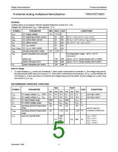
see Figs 6 and 7
see Figs 6 and 7
DC supply voltage VCC − VEE
DC input voltage range
2.0
GND
VEE
VS
DC switch voltage range
VCC
Tamb
operating ambient temperature −40
+85 −40
+85 °C
range
see DC and AC
CHARACTERISTICS
Tamb
tr, tf
operating ambient temperature −40
range
+125 −40
+125 °C
input rise and fall times
1000
500
400
250
VCC = 2.0 V
VCC = 4.5 V
VCC = 6.0 V
VCC = 10.0 V
6.0
6.0 500
ns
December 1990
5

 NXP [ NXP ]