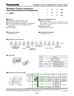
Multilayer Ceramic Capacitors(For General Usage)
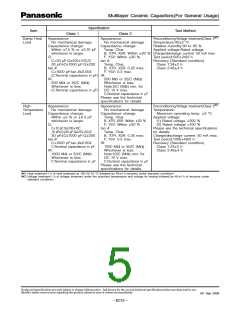
■ Specifications and Testing Methods
Specification
Item
Test Method
Class 1
Class 2
Operating
Temperature
Range
Temp. Char. C
Temp. Char. B, X7R
: –55 to 125 °C
Temp. Char. B, X5R
: –55 to 85 °C
Temp. Char. F, Y5V
: –30 to 85 °C
∆
: –55 to 125 °C
: –25 to 85 °C
Temp. Char. SL
: –55 to 125 °C
Dielectric
Withstanding
Voltage
No dielectric breakdown and /or damage
Test voltage:
Class 1:Rated voltage 300 %
҂
Class 2:Rated voltage 250 %
҂
Duration:1 to 5 s
Charge/discharge current : 50 mA max.
Insulation
Resistance
(I R)
10000 M or 500/C (M ) whichever is less.
Measuring voltage:Rated voltage
Duration: 60 5 s
Charge/discharge current : 50 mA max.
ȑ
ȑ
Note:100/C(M )min. for DC 10 V max.
ȑ
C:Nominal Cap. in µF
Capacitance Within the specified tolerance.
Measuring temperature: 20 2 °C
Class 1:
Q Factor or
Dissipation
Factor
Q:
tan :
δ
C<30 pF: Q 400+20C
Temp. Char. B, X7R, X5R:
0.15 max.
>
Nominal capacitance
C
1000 pF C > 1000 pF
<
30 pF C 1000 pF:Q 1000
<
<
>
Measuring frequency 1 MHz 10 % 1 kHz 10 %
Measuring voltage 0.5 to 5 Vrms 0.5 to 5 Vrms
(tan
)
Temp. Char. F, Y5V:
0.2 max.
Please see the technical
specifications for details.
δ
tan
:
δ
C>1000 pF: tan
0.002
δ<
Class 2:
Preconditioning: The capacitors shall be kept
in temperature of 150 +0/–10 °C for 1 hour
(C:Nominal Cap. in pF)
✽
and subjected to standard condition 48 4
hours before initial measurement.
Nominal capacitance
C < 1 µF
Measuring frequency 1 kHz 10 %
Measuring voltage 1.0 0.2 Vrms
Temperature
Characteristics
Temp. Char.
Temp. Char.
Maximum capacitance change at stage 1 to 5
CG : 0 30 ppm/ °C
CH : 0 60 ppm/ °C
CJ : 0 120 ppm/ °C
CK : 0 250 ppm/ °C
SL : +350 to –1000 ppm/ °C
B
:
10 %
Temp. C , SL
∆
B, F
X7R X5R Y5V
X7R : 15 %
X5R : 15 %
Char.
1
20 °C 25 °C 25 °C 25 °C
–25 °C –55 °C –55 °C –30 °C
F
: +30, –80 %
2
Y5V : +22, –82 %
3
20 °C 25 °C 25 °C 25 °C
(Ref. Temp.)
4
5
85 °C 125 °C 85 °C 85 °C
20 °C 25 °C 25 °C 25 °C
See the technical specifications for
details such as measuring voltage.
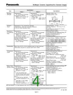
Adhesion
Terminal electrodes shall be free from peeling or signs of
peeling.
Applied force:
Size: 0201: 2 N
Size: 0402 to 0805: 5N
Duration: 10 s
Size: 0201 to 0402
0.3/Size:0201
0.5/Size:0402
1.0
0.5R
PC board
Sample
Size: 0603 to 0805
Sample
Unit : mm
✽Standard conditions : Temperature 15 to 35 °C, Relative humidity 45 to 75 %
Design and specifications are each subject to change without notice. Ask factory for the current technical specifications before purchase and/or use.
Should a safety concern arise regarding this product, please be sure to contact us immediately.
00 Sep. 2008
– EC10 –

 PANASONIC [ PANASONIC ]