To be transferred to Honda Tsushin kogyo Co.,Ltd. from October 1, 2009
AXA2R
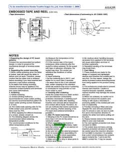
EMBOSSED TAPE AND REEL (Unit: mm)
• Tape dimensions
• Reel dimensions (Conforming to JIS C0806-1995)
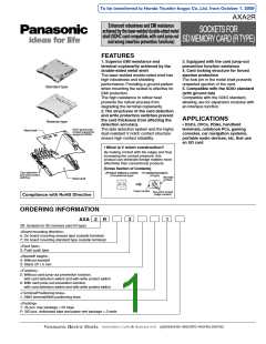
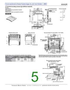
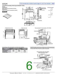
Socket for SD memory card
Emboss
carrier tape
Taping reel
(44.4)+2
Top cover tape
0
Top cover
tape
Tape
Emboss carrier tape
Cavity
Label
(1.75)
20.20
40.40
44.00
NOTES
1.Regarding the design of PC board
patterns
(6) Measure the temperature at the
connector surface.
2) Be cautious when handling because
excessive force applied to the terminals
will cause deformation and loss of
terminal coplanarity.
3) Repeated bending of the terminals
may break them.
Conduct the recommended foot pattern
design, in order to preserve the
mechanical strength of terminal solder
areas.
(7) If the reverse side of the board
undergoes reflow soldering after the
socket is reflow-soldered, fix the socket
with tape or adhesive; otherwise, the
socket may drop. The socket can
withstand two iterations of reflow
soldering.
2. Regarding the socket mounting
1) When reflow soldering when the slider
is locked, heat will cause the slider to
deform and not work. Therefore, please
confirm that the slider lock is released
before mounting if you have inserted and
removed a card before soldering.
2) Be aware that during mounting,
external forces may be applied to the
connector contact surfaces and terminals
and cause deformations.
7. Card fitting
1) These products are made for the
design of compact and lightweight
devices and therefore the molded part is
very thin. For this reason, design the
device to prevent undue wrenching forces
from being applied to the product during
use.
2) The sockets are constructed to prevent
reverse card insertion. Caution is
required because repeated, mistaken
reverse insertion may damage the socket
and card.
3) When not soldered, be careful not to
insert and remove the socket’s card.
Doing so will cause a decrease in
anchoring ability of the molded part and
loss of coplanarity.
4) Forcibly removing a fitted card may
degrade the card removal prevention
lock. To remove a card, be sure to push
the card in the insertion direction to
release the slider lock before pulling out
the card.
2) Hand soldering
• Set the soldering tip to 300°C, and
solder for no more than 5 seconds.
• Be aware that for the 0 mm standoff
type, solder creeping at the retention
solder tab sections may occur if soldering
is conducted for long periods or if too
much solder is used.
3. Soldering
1) Reflow soldering
4. Cleaning after soldering
Inside the socket there is a slider section
and card detection contact/write
protection mechanism. If anything such
as flux remains inside after washing,
insertion and removal will be hampered
and contact will be faulty. Therefore, do
not use methods that involve submersion
when cleaning. (Partial cleaning of the
PC board and soldered terminals is
possible.)
(1) Screen-printing method is
recommended for cream solder printing.
(2) Use the recommended foot pattern for
cream solder printing (screen thickness:
0.12 mm).
(3) The metal mask opening ratio for the
COM contact (one) and NO contacts
(two) must be 75%.
(4) When applying the different thickness
of a screen, please consult us.
(5) The following diagram shows the
recommended reflow soldering
temperature profile.
5. After PC board mounting
1) Warping of the PC board should be no
more than 0.03 mm for the entire
connector length.
5) Please include notes to the following
effect in your user manuals.
The recommended conditions for the
reflow temperature profile
2) When assembling PC boards or
storing them in block assemblies, make
sure that undue weight is not exerted on
a stacked socket.
3) Be sure not to allow external pressure
to act on sockets when assembling PC
boards or moving in block assemblies.
6. Handling single components
1) Make sure not to drop or allow parts to
fall from work bench
6) The card ejection protection lock does
not work for MMC.
7) The socket does not have a wrong
insertion protection structure for MMC.
Be careful about the insertion direction.
8) If an MMC is inserted, it is possible
that a short circuit between the socket’s
signal contacts No. 7 and 8 and the
MMC’s contact No. 7 may be caused.
Temperature
Peak temperature
250°C max.
180 to 200°C
Preheating
155 to 165°C
60 to 120 sec.
Within 30 sec.
Time
panasonic-electric-works.net/ac

 PANASONIC [ PANASONIC ]