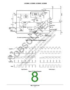
UC3844, UC3845, UC2844, UC2845
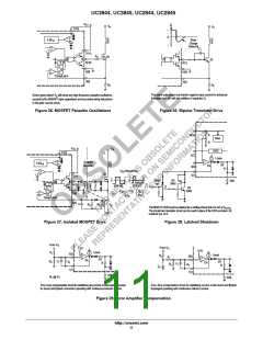
V = 15V
in
+
UC3845
Output Load Regulation
(open loop configuration)
7(12)
47
I
O
(mA)
V (V)
O
34V
8(14)
+
Reference
Regulator
ꢂ0
ꢂ2
ꢂ9
18
36
29.9
28.8
28.3
27.4
24.4
−
V
CC
UVLO
+
1N5819
R
R
Internal
Bias
−
2.5V
+
7(11)
6(10)
5(8)
−
+
10k
V
ref
UVLO
3.6V
−
15 10
1N5819
4(7)
Oscillator
V
O
ꢀ 2 (V )
in
+
+
T
47
+
1.0nF
Connect to
Pin 2 for
closed loop
operation.
0.5mA
S
R2
2R
+
−
Q
2(3)
1(1)
−
+
R
PWM
Latch
Error
Amplifier
R
1.0V
3(5)
R2
R2
V
R1
O = 2.5
+ 1
Current Sense
Comparator
5(9)
The capacitor’s equivalent series resistance must limit the Drive Output current to 1.0 A. An additional series
resistor may be required when using tantalum or other low ESR capacitors. The converter’s output can provide
excellent line and load regulation by connecting the R2/R1 resistor divider as shown.
Figure 31. Step−Up Charge Pump Converter
V = 15V
in
+
UC3845
7(12)
47
34V
8(14)
+
Reference
Regulator
−
V
CC
UVLO
+
R
R
Internal
Bias
−
2.5V
+
7(11)
−
+
10k
V
ref
UVLO
3.6V
−
15 10
1N5819
+
4(7)
6(10)
+
Oscillator
V
ꢀ − (V )
O
in
T
1N5819
47
+
1.0nF
0.5mA
5(8)
S
2R
+
−
Q
2(3)
1(1)
−
+
R
PWM
Latch
Output Load Regulation
Error
Amplifier
R
1.0V
3(5)
I
O
(mA)
V (V)
O
ꢂ0
ꢂ2
ꢂ9
18
32
−14.4
−13.2
−12.5
−11.7
−10.6
Current Sense
Comparator
5(9)
The capacitor’s equivalent series resistance must limit the Drive Output current to 1.0 A.
An additional series resistor may be required when using tantalum or other low ESR capacitors.
Figure 32. Voltage−Inverting Charge Pump Converter
http://onsemi.com
13

 ONSEMI [ ONSEMI ]