NCV7703
CSB SCLK
NCV7703
CSB SCLK
CSB SCLK
NCV7708
CSB SCLK
NCV7708
NCV7703
SI
SO
SI
SO
SI
SO
SI
SO
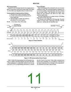
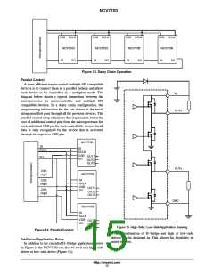
Figure 13. Daisy Chain Operation
Parallel Control
A more efficient way to control multiple SPI compatible
devices is to connect them in a parallel fashion and allow
each device to be controlled in a multiplex mode. The
diagram below shows a typical connection between the
microprocessor or microcontroller and multiple SPI
compatible devices. In a daisy chain configuration, the
programming information for the last device in the serial
string must first pass through all the previous devices. The
parallel control setup eliminates that requirement, but at the
cost of additional control pins from the microprocessor for
each individual CSB pin for each controllable device. Serial
data is only recognized by the device that is activated
through its respective CSB pin.
V
S
OUTx
NCV7703
SI
SCLK
SI
SCLK
CSB
SO
OUT1
OUT2
OUT3
SO
OUTx
CSB
NCV7703
SI
chip1
CSB
SCLK
CSB
SO
chip2
OUT1
OUT2
OUT3
CSB
chip3
GND
NCV7703
SI
SCLK
CSB
SO
OUT1
OUT2
OUT3
Figure 15. High−Side / Low−Side Application Drawing
Figure 14. Parallel Control
Any combination of H−bridge and high or low−side
drivers can be designed in. This allows for flexibility in
many systems.
Additional Application Setup
In addition to the cascaded H−Bridge application shown
in Figure 1, the NCV7703 can also be used as a high−side
driver or low−side driver (Figure 15).
http://onsemi.com
15

 ONSEMI [ ONSEMI ]