NCS37020
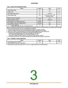
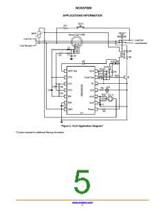
Functional Description (refer to application circuit, Figure 2)
The NCS37020 provides for a single IC controller
solution for ground fault protection and self−test auto
monitoring per UL standard UL943B.
The key internal blocks include: 12 V shunt regulator,
precision bandgap reference, two 3.3 V linear regulators
(one for the digital and one for the analog circuit), CT sense
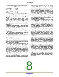
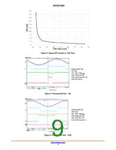
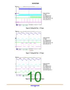
The first self−test (ST) cycle will occur at one second and
thereafter every 12 minutes. During the ST cycle, the Fault
Test pin will be enabled during the positive half cycle and the
CT current (set at 12 mA, R8) will be verified. During the
next negative half cycle, the SCR’s anode voltage will be
pre−biased by the SCR Test pin to 3.3 volts. The SCR will
then be enabled and the SCR’s anode voltage will be
monitored by the SCR Test pin. If the anode voltage goes
below 2.1 volts, the SCR will be disabled after a 400 ms
verification check and the ST logic will register a passing ST
cycle. Figure 2 shows two SCRs in series. A redundant SCR
is required during the SCR anode to cathode short test to
prevent the solenoid from burn out damage. The SCR
self–test cycle will fail if either SCR Q1A or Q1B are open.
If either Q1A or Q1B are shorted (anode to cathode) the ST
cycle will pass, however, the GF function will also function
correctly. The next ST cycle will occur in 12 minutes. Note
that when the SCR is enabled, the blocking diode D5 will
prevent the solenoid from being energized and opening the
load contacts. If either the GF (ground fault) or SCR
self−test cycles fail, these self−test cycles will be repeated
for up to three more consecutive cycles. If any consecutive
GF and SCR tests pass, the ST logic will register a passing
self−test cycle. If all four ST consecutive cycles fail, a ST
cycle will be repeated at 2, 3 and 4 seconds for a total of 16
self−test cycles. If all 16 ST cycles fail, a ST EOL fault will
occur. The SCR will be enabled for four consecutive positive
half cycles, then the LED will blink at 4 Hz. The LED will
only be biased during the positive AC half wave cycle. The
SCR will be enabled for one positive half cycle every 4.5
seconds. A self−test cycle will occur every second. If a
self−test cycle passes, the ST EOL logic will be reset (power
on reset state). If a ground fault is detected during a ST EOL
state, the EOL logic will be reset. This allows for resetting
the ST EOL state by pressing the manual test button when
the load contacts are closed.
amplifier with V dynamic cancellation, 1.65 V reference
OS
for the CT, 2 MHz oscillator dynamically trimmed to the AC
line frequency, 8 bit SAR ADC, comparators, digital filters
and digital control logic.
The internal shunt regulator clamps the SUP pin voltage
at 12 volts. This provides the bias voltage for the analog and
digital internal circuitry via two 3.3 V linear regulators. The
NCS37020 controller can be biased full wave or half wave.
Figure 2 shows a half wave bias application. Half wave bias
allows for lower wattage bias resistors (R1A and R1B) and
less redundant bias diodes. The D1−4 diodes are biased so
that only during the positive half cycle the capacitor C1 will
be charged to 12 volts. During the negative half cycle, C1
will supply the bias current for the NCS37020. To minimize
the NCS37020 bias current during the negative half cycle,
the SCR and LED outputs will only be enabled during the
positive half cycle. The D1−4 diodes and R1A−R1B
resistors include redundant components to pass the UL943B
standard.
At POR (power on reset) detection (SUP>4 V) the logic
is reset and the bias circuitry is enabled. The Phase pin
continually checks for an input signal. There is a 1 mA pull
down internal current source connected to this pin so a
floating or open pin will be biased low. If there is no
50/60 Hz signal detected on this pin for greater than 32 ms
due to an open solenoid or open R2 resistor, a “no clock” End
of Life (EOL) fault will occur. After ~150 ms, the LED
indicator logic will be enabled and blink at 4 Hz. The SCR
will be enabled for one positive half cycle every 4 seconds.
The “no clock” EOL logic state will continue until a POR
occurs or a 50/60 Hz signal is detected on the Phase pin.
When a 50/60 Hz signal is detected, the no clock EOL state
will be reset and a ST (self−test) cycle will occur after 75 ms.
If this ST cycle passes, the next ST cycle will occur in 12
minutes. If four consecutive no clock ST cycles fail, a ST
EOL fault will occur. During a no clock EOL state, the phase
information will be detected by the shunt regulator’s bias
circuitry. The shunt regulator will detect an AC zero cross by
monitoring the Shunt regulator’s clamp current. When the
VAC voltage crosses ~80 volts, a zero cross is registered by
the shunt regulator’s circuitry.
The above no clock and GF/SCR self−test functions
rd
provide for full UL943B (3 Edition) compliance for the
auto monitoring requirement. The NCS37020 IC controller
tests for the CT, solenoid, clock input, SCR and bias
circuitry.
The CT is biased at 1.65 volts. The CT sense amplifier
monitors the ground fault current. This current is converted
to a voltage level at the CTO pin which is the input to the
ADC (IDF pin). The resistor R5 sets the GF threshold per the
following equation:
ǒ
Ǔ
0.203 CT1 RCT1 ) R7 ) 2pfACLCT1
Note, the “no clock” EOL logic can be used in production
testing for generation of an EOL state and enabling the LED
indicator. If a DC voltage greater than ~75 volts is applied
to the Line Hot input, the NCS37020 will be biased correctly
but will not see a zero cross signal and a “no clock” ST EOL
failure will occur. The LED will be enabled within 150 ms.
Idiff
+
(eq. 1)
ǒ
Ǔ
R5 RCT1 ) 2pfACLCT1
CT = Turns ratio of differential CT
1
R
CT1
= DC winding resistance of differential CT
f
= AC mains frequency
AC
L
= Inductance of differential CT
CT1
www.onsemi.com
7

 ONSEMI [ ONSEMI ]