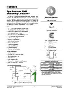
NCP3170
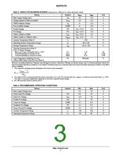
Table 2. ABSOLUTE MAXIMUM RATINGS (measured vs. GND pin 3, unless otherwise noted)
Rating
Symbol
V
V
Unit
V
MAX
MIN
Main Supply Voltage Input
V
IN
20
−0.3
−0.3
−0.3
−0.3
−0.3
−0.3
−0.7
−5
Voltage between PGND and AGND
PWM Feedback Voltage
Error Amplifier Voltage
V
PAG
0.3
V
F
B
6
V
COMP
EN
6
V
Enable Voltage
V
V
V
+ 0.3 V
+ 0.3 V
+ 0.3 V
+ 10 V
V
IN
IN
IN
PG Voltage
PG
V
VSW to AGND or PGND
VSW to AGND or PGND for 35ns
Junction Temperature (Note 1)
Operating Ambient Temperature Range
Storage Temperature Range
V
SW
V
V
SWST
V
V
IN
T
J
+150
°C
°C
°C
T
A
−40 to +85
T
stg
− 55 to +150
Thermal Characteristics (Note 2)
SOIC−8 Plastic Package
Maximum Power Dissipation @ T = 25°C
P
q
RqJC
1.15
87
37.8
W
°C/W
°C/W
A
D
JA
Thermal Resistance Junction-to-Air
Thermal Resistance Junction-to-Case
R
Lead Temperature Soldering (10 sec):
Reflow (SMD Styles Only) Pb-Free (Note 3)
RF
260 peak
°C
Stresses exceeding Maximum Ratings may damage the device. Maximum Ratings are stress ratings only. Functional operation above the
Recommended Operating Conditions is not implied. Extended exposure to stresses above the Recommended Operating Conditions may affect
device reliability.
1. The maximum package power dissipation limit must not be exceeded.
TJ(max) * TA
PD
+
RqJA
2. The value of qJA is measured with the device mounted on 2in x 2in FR−4 board with 2oz. copper, in a still air environment with T = 25°C.
A
The value in any given application depends on the user’s specific board design.
3. 60−180 seconds minimum above 237°C.
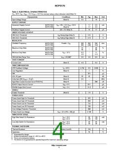
Table 3. RECOMMENDED OPERATING CONDITIONS
Rating
Symbol
Min
4.5
Max
18
Unit
V
Main Supply Voltage Input
Power Good Pin Voltage
Switch Pin Voltage
PG
4.5
18
V
V
SW
−0.3
0
18
V
Enable Pin Voltage
EN
COMP
FB
18
V
Comp Pin Voltage
−0.1
−0.1
−0.1
−40
−40
5.5
5.5
−0.1
125
85
V
Feedback Pin Voltage
Power Ground Pin Voltage
Junction Temperature Range
Operating Temperature Range
V
PGND
V
T
J
°C
°C
T
A
http://onsemi.com
3

 ONSEMI [ ONSEMI ]