NCP1396A, NCP1396B
ELECTRICAL CHARACTERISTICS
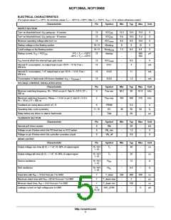
(For typical values T = 25C, for min/max values T = --40C to +125C, Max T = 150C, V = 12 V, unless otherwise noted.)
J
J
J
CC
TIMERS
Characteristic
Pin
Symbol
Itimer
Min
--
Typ
160
25
1.4
4
Max
--
Unit
mA
ms
s
Timer charge current
3
3
3
3
3
1
1
Timer duration with a 1 mF capacitor and a 1 MΩ resistor
Timer recurrence in permanent fault, same values as above
Voltage at which pin 3 stops output pulses
Voltage at which pin 3 re--starts output pulses
Soft--start ending voltage
T--timer
T--timerR
VtimerON
VtimerOFF
VSS
--
--
--
--
3.5
0.9
--
4.4
1.1
--
V
1
V
2
V
Soft--start charge current
0C < T < +125C
ISS
80
75
110
110
125
130
mA
J
-- 4 0 C < T < +125C
J
Soft--start duration with a 100 nF capacitor (Note 3)
1
T--SS
--
1.8
--
ms
PROTECTION
Characteristic
Pin
8--9
8--9
8--9
Symbol
VrefFaultF
HysteFaultF
VrefFaultS
Min
1.00
--
Typ
1.05
80
Max
1.10
--
Unit
V
Reference voltage for fast input (Note 4)
Hysteresis for fast input (Note 4)
Reference voltage for slow input
mV
V
0C < T < +125C
0.95
0.92
1.00
1.00
1.05
1.05
J
-- 4 0 C < T < +125C
J
Hysteresis for slow input
8--9
8
HysteFaultS
TpFault
IBObias
VBO
--
--
60
55
--
90
--
mV
ns
mA
V
Propagation delay for fast fault input drive shutdown
Brown--Out input bias current
5
--
0.02
1.04
Brown--Out level (Note 4)
5
0.99
1.09
Hysteresis current, Vpin5 > VBO – A version
0C < T < +125C
5
IBO_A
21.5
19
26.5
26.5
31.5
33
mA
J
-- 4 0 C < T < +125C
J
Hysteresis current, Vpin5 > VBO – B version
0C < T < +125C
5
IBO_B
86
80
106
106
126
132
mA
J
-- 4 0 C < T < +125C
J
Latching voltage
Temperature shutdown
Hysteresis
5
--
--
Vlatch
TSD
3.6
140
--
4
--
4.4
--
V
C
C
TSDhyste
30
--
3. The A version does not activate soft--start (unless the feedback pin voltage is below 0.6 V) when the fast--fault is released, this is for skip cycle
implementation. The B version does activate the soft--start upon release of the fast--fault input for any feedback conditions.
4. Guaranteed by design
http://onsemi.com
6

 ONSEMI [ ONSEMI ]