NCP1396A, NCP1396B
HV
R17
R8
R24
D4
R23
FB
OVP
+
C6
M1
R20
U2A
U5
U3A
1
2
3
4
5
6
7
16
15
14
R10
L1
Vout
R12
C12
R4
D1
D2
D8
R21
+
12
11
10
Rt
M2
C2
R5
FB
R1
R11
D9
OVP
R7
8
9
T1
C13
Slow Input
Fast
Input
U2B
R3
U3B
C4
Fmax
C8
D6
D7
D3
C11
C10
+
C7
C9
C3
C1
C14
U1
R2
R22
R16
R19
R9 R14
Timer
R18
R13 R6
BO DT
Soft--
start
Skip
Selection
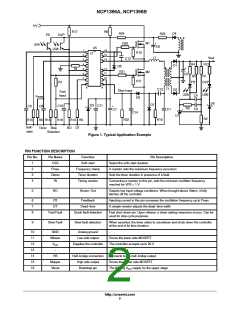
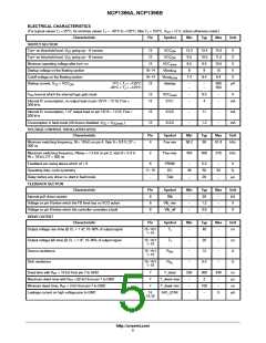
Figure 1. Typical Application Example
PIN FUNCTION DESCRIPTION
Pin No.
Pin Name
CSS
Function
Soft--start
Pin Description
1
2
3
4
Select the soft--start duration
Fmax
Ctimer
Rt
Frequency clamp
Timer duration
Timing resistor
A resistor sets the maximum frequency excursion
Sets the timer duration in presence of a fault
Connecting a resistor to this pin, sets the minimum oscillator frequency
reached for VFB = 1 V
5
BO
Brown--Out
Detects low input voltage conditions. When brought above Vlatch, it fully
latches off the controller.
6
7
8
FB
DT
Feedback
Dead--time
Injecting current in this pin increases the oscillation frequency up to Fmax.
A simple resistor adjusts the dead--time width
Fast Fault
Quick fault detection
Fast shut--down pin. Upon release, a clean startup sequence occurs. Can be
used for skip cycle purposes.
9
Slow Fault
Slow fault detection
When asserted, the timer starts to countdown and shuts down the controller
at the end of its time duration.
10
11
12
13
14
15
16
GND
Analog ground
Low side output
Supplies the controller
--
--
Mlower
Drives the lower side MOSFET
The controller accepts up to 20 V
--
V
CC
--
HB
Half--bridge connection
High side output
Bootstrap pin
Connects to the half--bridge output
Drives the higher side MOSFET
Mupper
Vboot
The floating V supply for the upper stage
CC
http://onsemi.com
2

 ONSEMI [ ONSEMI ]