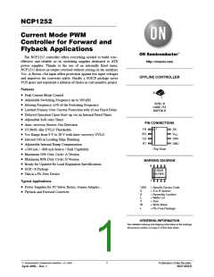
NCP1252
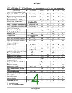
Table 4. ELECTRICAL CHARATERISTICS
(V = 15 V, R = 43 kW, C
= 1 nF. For typical values T = 25°C, for min/max values T = –25°C to +125°C, unless otherwise noted)
CC
T
DRV
J
J
Characteristics
Test Condition
Symbol
Min
Typ
Max
Unit
DRIVE OUTPUT
Output voltage fall−time
V
= 15 V, C
= 1nF,
t
f
−
−
−
22
15
50
−
ns
V
CC
DRV
90 to 10%
Clamping voltage (maximum gate voltage)
V
= 25 V
V
CL
18
CC
R
R
= 47 kW, C
= 1 nF
DRV
DRV
High−state voltage drop
V
= V
+ 100 mV,
V
500
mV
CC
DRV
CC(min)
DRV(clamp)
= 47 kW, C
= 1 nF
DRV
CYCLE SKIP
Skip cycle level
Skip threshold Reset
V
0.2
0.3
0.4
V
V
skip
V
−
V
skip
+
−
skip(reset)
V
skip(HYS)
Skip threshold Hysteresis
V
−
25
−
mV
skip(HYS)
SOFT START
Soft−start charge current
SS pin = GND
I
8.8
3.5
10
4.0
120
11
4.5
155
mA
V
SS
Soft start completion voltage threshold
V
SS
Internal delay before starting the Soft start
SS
100
ms
delay
when V
is reached
CC(on)
PROTECTION
Current sense fault voltage level triggering
the timer
F
0.9
10
1
15
1
1.1
20
V
CS
Timer delay before latching a fault (overload
or short circuit)
When CS pin > F
T
I
ms
CS
fault
Brown−out voltage
V
0.974
1.026
V
BO
Internal current source generating the
Brown−out hysteresis
−5°C ≤ T ≤ +125°C
8.8
8.6
10
10
11.2
11.2
mA
J
BO
−25°C ≤ T ≤ +125°C
J
3. Guaranteed by design
4. V
, R
Guaranteed by design
ramp
ramp
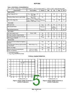
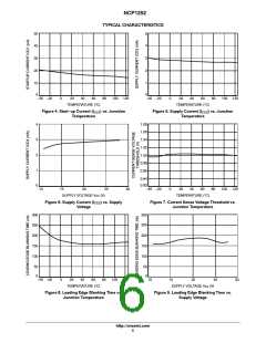
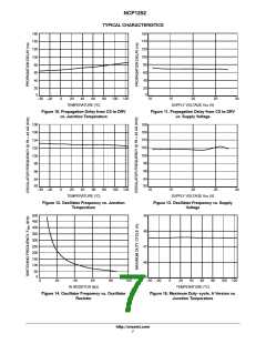
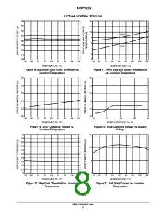
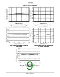
TYPICAL CHARACTERISTICS
1.20
1.15
1.10
1.05
1.00
10.2
10.0
9.8
9.6
9.4
9.2
VCC(on)
0.95
0.90
VCC(off)
9.0
8.8
−40 −20
0
20
40
60
80
100
120
−40 −20
0
20
40
60
80
100 120
TEMPERATURE (°C)
TEMPERATURE (°C)
Figure 2. Supply Voltage Threshold vs.
Junction Temperature
Figure 3. Supply Voltage Hysteresis vs.
Junction Temperature
http://onsemi.com
5

 ONSEMI [ ONSEMI ]