NCP1252
Vbulk
Vout
NCP1252
1
8
7
6
5
Vcc
2
3
4
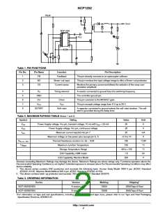
Table 1. PIN FUNCTIONS
Pin No.
Pin Name
FB
Function
Pin Description
1
2
3
Feedback
This pin directly connects to an optocoupler collector.
BO
Brown−out input
This pin monitors the input voltage image to offer a Brown−out protection.
CS
Current sense
Monitors the primary current and allows the selection of the ramp com-
pensation amplitude.
4
5
6
7
8
R
Timing element
A resistor connected to ground fixes the switching frequency.
The controller ground pin.
T
GND
Drv
−
Driver
This pin connects to the MOSFET gate
V
CC
V
CC
This pin accepts voltage range from 8 V up to 28 V
SSTART
Soft−start
A capacitor connected to ground selects the soft−start duration. The soft
start is grounded during the delay timer
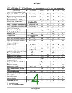
Table 2. MAXIMUM RATINGS TABLE (Notes 1 and 2)
Symbol Rating
Power Supply voltage, Vcc pin, transient voltage: 10 ms with I
Value
30
Unit
V
V
CC
V
CC
< 20 mA
Vcc
Power Supply voltage, Vcc pin, continuous voltage
Maximum current injected into pin 7
Maximum voltage on low power pins (except pin 6, 7)
Thermal Resistance Junction−to−Air – SO8
Maximum Junction Temperature
28
V
I
20
mA
V
Vcc
−0.3 to 10
180
R
°C/W
°C
°C
kV
V
θ
J−A – SO
TJ
150
MAX
Storage Temperature Range
−60 to +150
1.8
ESD Capability, HBM model
ESD Capability, Machine Model
200
Stresses exceeding Maximum Ratings may damage the device. Maximum Ratings are stress ratings only. Functional operation above the
Recommended Operating Conditions is not implied. Extended exposure to stresses above the Recommended Operating Conditions may affect
device reliability.
1. This device series contains ESD protection and exceeds the following tests: Human Body Model 1800 V per JEDEC Standard
JESD22−A114E. Machine Model Method 200 V per JEDEC Standard JESD22−A115A.
2. This device contains latch−up protection and exceeds 100 mA per JEDEC Standard JESD78.
Table 3. ORDERING INFORMATION
†
Device
Version
A version
B version
Marking
1252A
Shipping
NCP1252ADR2G
NCP1252BDR2G
2500/Tape & Reel
2500/Tape & Reel
1252B
†For information on tape and reel specifications, including part orientation and tape sizes, please refer to our Tape and Reel Packaging
Specification Brochure, BRD8011/D.
http://onsemi.com
2

 ONSEMI [ ONSEMI ]