NCP1236
VHV
VHV(start)
Waits
next
VCC(on)
before
starting
VHV(min)
time
VCC
VCC(on)
VCC(min)
HV
current
source =
Istart1
HV
current
source =
Istart2
VCC(inhibit)
time
time
DRV
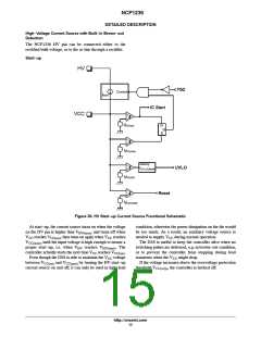
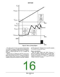
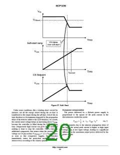
Figure 31. Start−up Timing Diagram
For safety reasons, the start−up current is lowered when
the HV current source will always turn on and off to maintain
between V and V
V
is below V
, to reduce the power dissipation in
V
CC
.
CC(on)
CC
CC(inhibit)
CC(min)
case the V pin is shorted to GND (in case of V capacitor
CC
CC
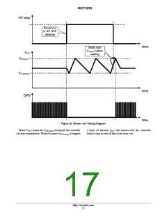
Brown−out protection
When the input voltage goes below V
brown−out condition is detected, and the controller stops.
The HV current source alternatively turns on and off to
failure, or external pull−down on V
to disable the
CC
, a
HV(stop)
controller).
There are only two conditions for which the current source
doesn’t turn on when V reaches V : the voltage on
CC
CC(min)
maintain V between V
and V
until the input
CC
CC(on)
CC(min)
HV pin is too low (below V ), or a thermal shutdown
HV(min)
voltage is back above V
.
HV(start)
condition (TSD) has been detected. In all other conditions,
http://onsemi.com
16

 ONSEMI [ ONSEMI ]