NCP1236
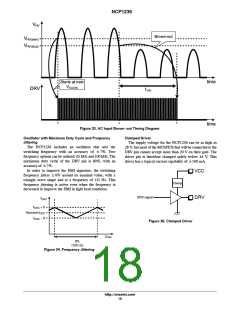
Typical Operation
further reduced. This allows minimizing the power
dissipation under extremely low load conditions. As the
skip mode is entered at very light loads, for which the
peak current is very small, there is no risk of audible
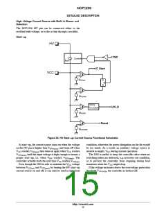
Start−up: The HV start−up current source ensures the
charging of the V capacitor up to the start−up
CC
threshold V
, until the input voltage is high
CC(on)
noise. V can be maintained between V
and
enough (above V
) to allow the switching to
CC
CC(on)
HV(start)
V
by the DSS, if the auxiliary winding does not
start. The controller then delivers pulses, starting with a
soft−start period t during which the peak current
CC(min)
provide sufficient level of V voltage under this
CC
SSTART
condition.
linearly increases before the current−mode control takes
over. During the soft−start period, the low level latch is
ignored, and the latch current is double, to ensure a fast
pre−charge of the Latch pin decoupling capacitor.
Overload: The NCP1236 features timer−based
overload detection, solely dependent on the feedback
information: as soon as the internal peak current
setpoint hits the V
clamp, an internal timer starts to
Normal operation: As long as the feedback voltage is
ILIM
count. When the timer elapses, the controller stops and
enter the protection mode, autorecovery for the B
version (the controller initiates a new start−up after
within the regulation range and V is maintained
CC
above V , the NCP1236 runs at a fixed frequency
CC(min)
(with jittering) in current−mode control. The peak
current (sensed on the CS pin) is set by the voltage on
the FB pin. Fixed ramp compensation is applied
internally to prevent sub−harmonic oscillations from
occurring.
t
elapses), or latched for the A version (the latch
autorec
is released if a brown−out event occurs or V is reset).
CC
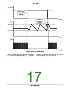
Brown−out: The NCP1236 features a true AC line
monitoring circuitry. It includes a minimum start−up
threshold and an autorecovery brown−out protection;
both of them independent of the ripple on the input
voltage. It can even work with an unfiltered, rectified
AC input. The thresholds are fixed, but they are
designed to fit most of the standard AC−DC conversion
applications.
Latch−off: When the Latch input is pulled up (typically
by an over−voltage condition), or pulled down
(typically by an over−temperature condition, using the
provided current source with an NTC), the controller
Light load operation: When the FB voltage decreases
below V
, typically corresponding to a load of
FB(foldS)
33 % of the maximum load (for a DCM design), the
switching frequency starts to decrease down to
f
. By lowering the switching losses, this feature
OSC(min)
helps to improve the efficiency in light load conditions.
The frequency jittering is enabled in light load
operation as well.
No load operation: When the FB voltage decreases
below V , typically corresponding to a load of 2
skip(in)
latches off. A voltage higher than V
pin has the same effect. The latch is released when a
on the VCC
% of the maximum load, the controller enters skip
mode. By completely stopping the switching while the
CC(ovp)
brown−out condition occurs, or when the V is reset.
feedback voltage is below V , the losses are
skip(out)
CC
http://onsemi.com
14

 ONSEMI [ ONSEMI ]