NCP1236
DETAILED DESCRIPTION
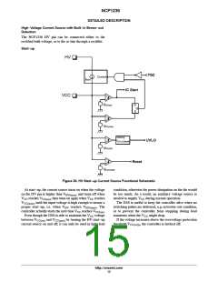
High−Voltage Current Source with Built−in Brown−out
Detection
The NCP1236 HV pin can be connected either to the
rectified bulk voltage, or to the ac line through a rectifier.
Start−up
HV
TSD
Control
Istart
IC Start
+
−
VCC
+
+
VCC(on)
R
Q
S
−
+
VCC(min)
blanking
UVLO(blank)
−
UVLO
t
+
+
+
VCC(off )
−
+
Reset
VCC(reset)
Figure 30. HV Start−up Current Source Functional Schematic
At start−up, the current source turns on when the voltage
on the HV pin is higher than V , and turns off when
condition, otherwise the power dissipation on the die would
be too much. As a result, an auxiliary voltage source is
HV(min)
V
V
reaches V
, then turns on again when V reaches
needed to supply V during normal operation.
CC
CC(on)
CC
CC
, until the input voltage is high enough to ensure a
CC(min)
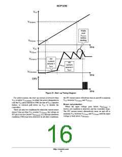
The DSS is useful to keep the controller alive when no
switching pulses are delivered, e.g. in brown−out condition,
or to prevent the controller from stopping during load
proper start−up, i.e. when V
controller actually starts the next time V reaches V
reaches V
. The
HV
HV(start)
.
CC
CC(on)
Even though the DSS is able to maintain the V voltage
transients when the V might drop.
CC
CC
between V
and V
by turning the HV start−up
If the voltage increases above the overvoltage protection
CC(on)
CC(min)
current source on and off, it can only be used in light load
threshold V
, the controller is latched off.
CC(ovp)
http://onsemi.com
15

 ONSEMI [ ONSEMI ]