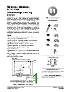
MC34064, MC33064, NCV33064
+
1.0k
+
−
2 (2)
2 (2)
Power
Supply
1 (1)
1 (1)
−
−
+
−
+
Solar
Cells
1.2V
1.2V
ref
ref
3 (4)
3 (4)
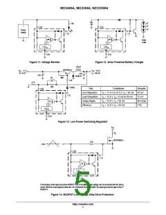
Figure 11. Voltage Monitor
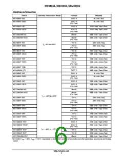
Figure 12. Solar Powered Battery Charger
25mH
MPSW51A
V
= 11.5
to 14.5V
V
= 5.0 V
= 50 mA
in
O
I
O
+
+
470
1N5819
470
22
+
680
1.2k
4.7k
330
1N756
Test
Conditions
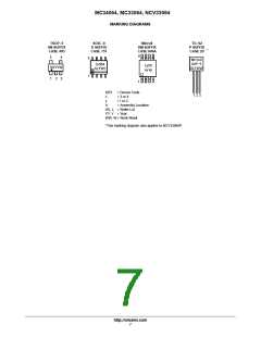
= 11.5 V to 14.5 V, I = 50 mA
Results
35 mV
12 mV
60 mVpp
77%
2 (2)
Line Regulation
Load Regulation
Output Ripple
Efficiency
V
in
V
in
V
in
V
in
O
1 (1)
= 12.6 V, I = 0 mA to 50 mA
O
−
+
= 12.6 V, I = 50 mA
O
= 12.6 V, I = 50 mA
O
1.2V
ref
3 (4)
Figure 13. Low Power Switching Regulator
V
CC
R
L
MTP3055EL
270
4.6V
2 (2)
1 (1)
−
+
1.2V
ref
3 (4)
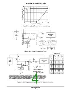
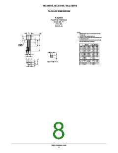
Overheating of the logic level power MOSFET due to insufficient gate voltage can be prevented with the above
2
circuit. When the input signal is below the 4.6 V threshold of the MC34064, its output grounds the gate of the L
MOSFET.
Figure 14. MOSFET Low Voltage Gate Drive Protection
http://onsemi.com
5

 ONSEMI [ ONSEMI ]