MC34064, MC33064, NCV33064
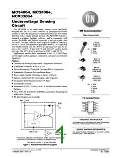
80
60
40
20
0
V
= 0 V
in
T = 25°C
A
0
0.4
0.8
V , FORWARD VOLTAGE (V)
1.2
1.6
Fꢀ
Figure 8. Clamp Diode Forward Current versus Voltage
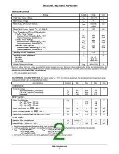
+
R
2 (2)
Reset
Power
Supply
Microprocessor
Circuit
1 (1)
C
DLY
−
−
+
A time delayed reset can be accomplished with the
addition of C . For systems with extremely fast
DLY
1.2 V
ref
power supply rise times (<500 ns) it is recommended
that the RC time constant be greater than 5.0 ms.
DLY
is the microprocessor reset input threshold.
V
th(MPU)
3 (4)
1
V
t
= RC In
DLY
th(MPU)
DLY
1 −
V
in
Figure 9. Low Voltage Microprocessor Reset
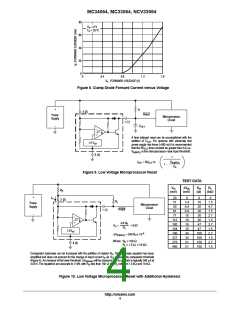
TEST DATA
V
(mV)
DV
(mV)
R
(W)
R
L
(kW)
H
th
H
R
H
+
I
in
20
51
0
0
0
2 (2)
R
L
3.4
6.8
6.8
10
10
16
16
34
34
51
51
10
1.5
4.7
1.5
2.7
1.5
2.7
1.5
2.7
1.5
2.7
1.5
Power
Supply
Microprocessor
Circuit
40
20
Reset
4.6 R
1 (1)
81
20
−
71
30
−
112
100
164
190
327
276
480
30
+
H
47
V
≈
+ 0.02
H
R
L
47
1.2V
ref
100
100
150
150
−6
DV
th(lower)
≈ 340 R x 10
H
Where:ꢁR ≤ 150 W
Where:ꢁR ≥ 1.5 W, ≤ 10 kW
H
3 (4)
L
Comparator hysteresis can be increased with the addition of resistor R . The hysteresis equation has been
H
simplified and does not account for the change of input current I as V crosses the comparator threshold
in
CC
(Figure 4). An increase of the lower threshold DV
will be observed due to I which is typically 340 mA at
in
th(lower)
4.59ꢂV. The equations are accurate to ±10% with R less than 150 W and R between 1.5 kW and 10 kW.
H
L
Figure 10. Low Voltage Microprocessor Reset with Additional Hysteresis
http://onsemi.com
4

 ONSEMI [ ONSEMI ]