MC10H109
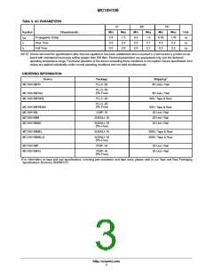
Table 3. AC PARAMETERS
0°
Min
0.4
25°
75°
Symbol
Characteristic
Max
1.3
2.0
2.0
Min
0.4
0.5
0.5
Max
1.3
2.1
2.1
Min
0.45
0.5
Max
1.45
2.2
Unit
ns
t
t
t
Propagation Delay
Rise Time
pd
0.5
ns
r
f
Fall Time
0.5
0.5
2.2
ns
NOTE: Device will meet the specifications after thermal equilibrium has been established when mounted in a test socket or printed circuit
board with maintained transverse airflow greater than 500 lfpm. Electrical parameters are guaranteed only over the declared
operating temperature range. Functional operation of the device exceeding these conditions is not implied. Device specification limit
values are applied individually under normal operating conditions and not valid simultaneously.
ORDERING INFORMATION
†
Device
Package
Shipping
MC10H109FN
PLLC−20
46 Units / Rail
PLLC−20
(Pb−Free)
MC10H109FNG
46 Units / Rail
MC10H109FNR2
PLLC−20
500 / Tape & Reel
PLLC−20
(Pb−Free)
MC10H109FNR2G
MC10H109L
500 / Tape & Reel
25 Unit / Rail
50 Unit / Rail
50 Unit / Rail
CDIP−16
MC10H109M
SOEIAJ−16
MC10H109MG
SOEIAJ−16
(Pb−Free)
MC10H109MEL
SOEIAJ−16
2000 / Tape & Reel
2000 / Tape & Reel
MC10H109MELG
SOEIAJ−16
(Pb−Free)
MC10H109P
PDIP−16
25 Unit / Rail
25 Unit / Rail
MC10H109PG
PDIP−16
(Pb−Free)
†For information on tape and reel specifications, including part orientation and tape sizes, please refer to our Tape and Reel Packaging
Specifications Brochure, BRD8011/D.
http://onsemi.com
3

 ONSEMI [ ONSEMI ]