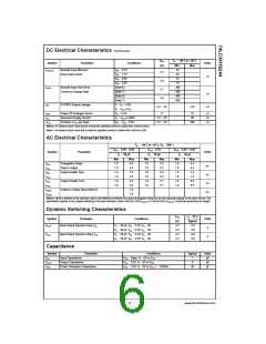
DC Electrical Characteristics (Continued)
V
T
40 C to 85 C
Min Max
CC
A
Symbol
Parameter
Bushold Input Minimum
Conditions
Units
(V)
I
I
I
V
V
V
V
0.7V
1.7V
0.8V
2.0V
45
45
I(HOLD)
IN
IN
IN
IN
2.3
Drive Hold Current
A
75
3.0
2.7
75
Bushold Input Over-Drive
Current to Change State
(Note 6)
(Note 7)
(Note 6)
(Note 7)
300
300
450
450
I(OD)
A
A
3.6
3-STATE Output Leakage
0
V
5.5V
or V
OZ
O
2.3 3.6
5.0
V
V
V
V
V
IH
I
IL
I
I
Power-Off Leakage Current
Quiescent Supply Current
5.5V
or GND
0
10
20
A
A
A
OFF
CC
O
I
V
2.3 3.6
2.3 3.6
CC
I
Increase in I per Input
V 0.6V
CC
500
CC
CC
IH
Note 6: An external driver must source at least the specified current to switch from LOW-to-HIGH.
Note 7: An external driver must sink at least the specified current to switch from HIGH-to-LOW.
AC Electrical Characteristics
T
40 C to 85 C, R
500
A
L
V
3.3V 0.3V
50 pF
V
2.7V
V
CC
2.5V 0.2V
CC
CC
Symbol
Parameter
Units
C
C
50 pF
C
L
30 pF
Max
L
L
Min
1.0
1.0
1.0
1.0
1.0
1.0
Max
4.5
4.5
5.5
5.5
5.4
5.4
1.0
1.0
Min
Max
5.2
5.2
6.3
6.3
5.7
5.7
Min
1.0
1.0
1.0
1.0
1.0
1.0
t
t
t
t
t
t
t
t
Propagation Delay
1.0
1.0
1.0
1.0
1.0
1.0
5.4
5.4
7.2
7.2
6.5
6.5
PHL
ns
ns
ns
ns
Data to Output
PLH
Output Enable Time
PZL
PZH
PLZ
Output Disable Time
PHZ
OSHL
OSLH
Output to Output Skew (Note 8)
Note 8: Skew is defined as the absolute value of the difference between the actual propagation delay for any two separate outputs of the same device. The
specification applies to any outputs switching in the same direction, either HIGH-to-LOW (t
) or LOW-to-HIGH (t
). Parameter guaranteed by design.
OSLH
OSHL
Dynamic Switching Characteristics
V
T
25 C
CC
A
Symbol
Parameter
Conditions
Units
(V)
3.3
2.5
3.3
2.5
Typical
0.8
V
Quiet Output Dynamic Peak V
C
C
C
C
50 pF, V
30 pF, V
50 pF, V
30 pF, V
3.3V, V
2.5V, V
3.3V, V
2.5V, V
0V
0V
0V
0V
OLP
OLV
OL
L
L
L
L
IH
IH
IH
IH
IL
IL
IL
IL
V
V
0.6
V
Quiet Output Dynamic Valley V
0.8
OL
0.6
Capacitance
Symbol
Parameter
Conditions
Typical
Units
pF
C
Input Capacitance
Output Capacitance
Power Dissipation Capacitance
V
V
V
Open, V 0V or V
CC
7
8
IN
CC
CC
CC
I
C
C
3.3V, V 0V or V
CC
pF
OUT
PD
I
3.3V, V 0V or V , f 10 MHz
20
pF
I
CC
5
www.fairchildsemi.com

 ONSEMI [ ONSEMI ]