AMIS-52150 Low-Power Transceiver with Clock and Data Recovery
Data Sheet
6.0 Pin Definitions
This section describes the pins of the AMIS-52000 package.
Table 8: Pin List
Pin#
Name
Type
RF
RF
Ana
Ana
Ana
Ana
Comments
Receive RF input 1
Receive RF input 2
Voltage controlled oscillator 2
Voltage controlled oscillator 1
Loop filter
1
2
3
4
5
6
RX1 RF
RX2 RF
VCO2
VCO1
LPFILT
RSSI/
Analog RSSI output or bandgap output
Bandgap Out
7
8
9
NC
CREF
GND
CLKOUT
X1
X2
IIC Data
NC
IIC Clock
TX/RX DATA
VDD
No electrical connection
Current bias precision resistor
Analog/digital ground
RC, XTAL, or data clock output
Xtal input
Ana
Ana
Dig
Ana
Ana
Dig
10
11
12
13
14
15
16
17
18
Xtal output
IIC interface data I/O
No electrical connection
IIC interface clock
Data transmit, data receive or recovered data
Positive power supply
Regulated voltage
Dig
Dig
Ana
Ana
RFPWR
Output for RF transmitter circuitry
19
20
RFOUT RF
RFGND
RF
Ana
Transmit RF output
RF ground
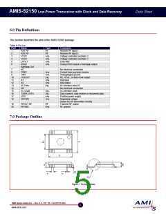
7.0 Package Outline
Figure 2: Package Outline
AMI Semiconductor – Rev 4.0, Oct. 06 – M-20535-004
5
www.amis.com

 ONSEMI [ ONSEMI ]