H8PS
Nomenclature
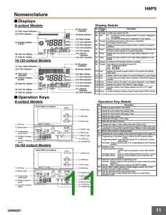
■ Displays
Display Details
8-output Models
No. Display
color
Description
(8) All protect
indication
(1) Cam output indicators
(2) PV/SV indicator
(1) Orange Lit while cam outputs are ON.
1
2
3
4
5
6
7
8
PRG
TST
RUN
(9) Mode indicator
(2) Red
PV: Lit while the present angular position or speed is displayed in
main display.
SV: Lit while the setting value is displayed in main display.
(10) Main display
(11) Unit indication
(12) 256 indication
(13) Unit indication
(3) Orange Lit while the start input is ON in Run or Test Mode.
Not lit when an error occurs.
(4) Rotation display
monitor
(4) Orange Displays Encoder present angular position, direction, and speed
guidelines.
(5) Green
(6) Green
(7) Green
Displays the bank number that is running in Run or Test Mode and
the bank number selected in Programming Mode.
(14) Sub-display
Displays the cam number for the angle setting displayed on sub-
display.
CAM
(15) ON/OFF
indication
(16) ADV indication
STEP
(6) Cam No. display
(7) Step No. display
Displays the step number for the angle setting displayed on sub-
display.
16-/32-output Models
(8) Orange Lit while the All Protection function is enabled.
(9) Orange The indicator for the selected mode is lit.
PRG: Programming Mode
TST: Test Mode
(8) All protect
indication
(1) Cam output indicators
(2) PV/SV indicator
RUN: Run Mode
(9) Mode indicator
1
2
3
4
5
6
7
8
9
10
PRG
TST
RUN
11 12 13 14 15 16 17 18 19 20
21 22 23 24 25 26 27 28 29 30
31 32
(10) Red
Displays the present angular position or the speed and settings
being made.
(3) Start input
indication
(10) Main display
(11) Unit indication
(11) Red
(12) Red
Displays units for the angle or the speed displayed on main display.
Lit while using an Encoder with a resolution of 256 if 256° display is
(4) Rotation display
monitor
selected.
(12) 256 indication
(13) Unit indication
(14) Sub-display
(13) Green
(14) Green
(15) Green
Displays units for the angle or the speed displayed on sub-display.
Displays the speed or the ON/OFF angle settings.
(5) Bank No. display
Indicates whether main display displays the ON or OFF angle
setting.
STEP
CAM
(15) ON/OFF
indication
(16) ADV indication
(6) Cam No. display
(7) Step No. display
(16) Green
Lit while setting the Advance Angle Compensation (ADV) Function.
■ Operation Keys
8-output Models
Operation Key Details
No.
Description
CHECK
1
Displays program details in Run Mode.
1. CHECK key
2
Selects the cam number with
Keys.
Keys.
3
Selects the step number with
Selects the bank number.
CAM
2. CAM keys
3. STEP keys
4
5
6
7
Selects the ON angle, or OFF angle
Writes the set data to memory.
STEP
STEP
CAM
11. ADV key
Changes the angle or other setting value with
Keys.
8
Connects the Cam Positioner to a personal computer via USB cable (order
separately) for programming with the Support Software (order separately).
ON
OFF
12. Mode switch
ADV
PRGM
5. ON/OFF key
TCH
MAN
TEST
RUN
ANGLE
WRITE
9
Moves to the screen for clearing settings
13. Programming
mode switch
6. WRITE key
CW
10 Designates the current angle of the machine (Encoder) as the origin (0°).
ANG
DSPL
1234
3
4
PLS/R
CLEAR
ORIGIN
ON ON 256 256
ON OFF 256 360
OFF ON 360 360
OFF OFF 720 360
7. ANGLE keys
ON
11 Programming or Test Mode:Press to shift to the ADV function setting
screen.
14. Rotation direction
switch
OFF
9. CLEAR key
CCW
DO NOT USE.
Programming Mode: Press and hold at least 3 s to shift to the Function
15. Encoder resolution
switch
Setting Mode.
10. ORIGIN key
Run Mode: Press and hold at least 5 s to enable/disable the All Protection
function.
16-/32-output Models
12 Switches modes.
Programming Mode (PRGM):
Used to write cam programs, set the ADV function,
CHECK
etc.
1. CHECK key
2. CAM keys
Test Mode (TEST): Used to modify settings while the Encoder is running.
Run Mode (RUN): Used for normal operation and to check the cam
program.
CAM
13 Select the method used for programming cams.
Teaching: ON/OFF Angles can be set based on actual machine (Encoder)
STEP
operation.
3. STEP keys
4. BANK key
Manual: ANGLE Keys can be used to set ON/OFF angles.
CAM
STEP
14 Sets the H8PS rotation direction (rotation display monitor, etc.) to the
machine (Encoder) rotation direction.
11. ADV key
ON
OFF
BANK
12. Mode switch
ADV
15 Sets the resolution of the connected Encoder.
Also sets the unit for angle display when using an Encoder with a
resolution of 256.
5. ON/OFF key
PRGM
TCH
TEST
ANGLE
ORIGIN
WRITE
MAN
RUN
13. Programming
mode switch
6. WRITE key
CW
ANG
DSPL
1234
3
4
PLS/R
CLEAR
ON ON 256 256
ON OFF 256 360
OFF ON 360 360
OFF OFF 720 360
7. ANGLE keys
ON
OFF
14. Rotation direction
switch
8. USB connector
9. CLEAR key
CCW
DO NOT USE.
15. Encoder resolution
switch
10. ORIGIN key
11

 OMRON [ OMRON ELECTRONICS LLC ]