K3HB-V
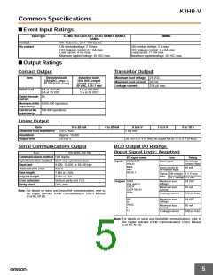
■ Input Ranges (Measurement Range and Accuracy)
Input type
Range
Set value
Measurement range
Input impedance
Accuracy
Allowable
instantaneous
overload (30 s)
K3HB-VLC
Load Cell, mV
A
B
a lc
0.00 to 199.99 mV
0.000 to 19.999 mV
100.00 mV
1 MΩ min.
0.1% rdg 1 digit max.
0.1% rdg 5 digits max.
0.1% rdg 3 digits max.
0.1% rdg 1 digit max.
200 V
b lc
c lc
d lc
C
D
199.99 mV
Note: 1. The accuracy is for an ambient temperature of 23±5°C. For all ranges,10% or less of max. input ±0.1% FS.
2. The letters “rdg” mean “reading.”
Input type
a lc
b lc
c lc
d lc
Connected
terminals
E2
E6
E3
E6
E4
E6
E5
E6
(mV)
199.99
199.99
200.000
150.000
100.000
50.000
0.00
100.00
19.999
0.000
0.00
−50.00
−100.00
−150.00
−200.00
−100.00
−199.99
Maximum
-19.99 to 219.99 mV -1.999 to 21.999 mV -110.00 to 110.00 mV -199.99 to 219.99 mV
measurement range
The area shown in dark shading indicates the factory setting.
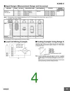
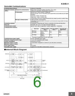
■ Load Cell Wiring Example
■ Scaling Example Using Range A
Indicated on the K3HB-V as 0 to 49N in the load cell specifications
(rated load 49N, recommended applied voltage 10 V, rated output
2 mV/V) (See note.)
+10 V (10-VDC, 100-mA
external power supply)
or
+5 V (5-VDC, 100-mA
external power supply)
B
E
Display value
+IN
Load cell
−IN
E2
E3
E4
E5
E6
Scaling values:
49 N
inp.a1=000.00
dsp.a1=00000
inp.a2=020.00
dsp.a2=49000
+OUT
+
−OUT
dp decimal point position: 00.000
B5
B6
Input value
20 mV
Note: “2 mV/V” indicates a load cell output of 2 mV for 1 V applied
voltage for the rated load (when using a load of 1 N). When the
applied voltage is 10 V, the load cell output is 20 mV (2 mV ×
10).
−
0 V
The precision can be increased by entering the A1 and A2 input
values by teaching, and then scaling the results.
4

 OMRON [ OMRON ELECTRONICS LLC ]