K3HB-V
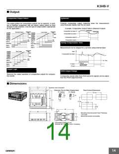
■ Connections
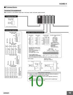
Terminal Arrangement
Note: Insulation is used between signal input, event input, output, and power supply terminals.
A
B
C
D
E
A
Operating Power Supply
1
2
3
4
5
6
100 to 240 VAC
24 VAC/ VDC
A1
A2
*Check the required power supply type.
B
Sensor Power Supply/Output
Sensor power supply +
C
Relays, Transistors, BCD and DeviceNet
PASS output
B1
Relay Outputs
<C1>
Relay Outputs
<C2>
Transistor Outputs
<T1> <T2>
DeviceNet Connector (Included)
<DRT>
PASS
B2
B3
B4
B5
B6
PNP
NPN
C1
C1
C2
HH
C1
C2
C3
C4
C5
C6
HH
H
N/C
C2
C3
C4
C5
C6
H
COM
L
+
H
C3
C4
C5
C6
PASS
L
−
<K33-
CPA>
<K33-
CPE>
<K33-
CPB>
1: V− (Power supply cable: Black)
2: CAN L (Communications cable: Blue)
3: Shield
4: CAN H (Communications cable: White)
5: V+ (Power supply cable: Red)
Applicable Connector:
HR31-5.08P-5SC (01)
(HIROSE ELECTRIC CO., LTD.)
* Attach the provided crimp terminals.
L
LL
LL
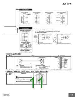
Sensor power supply +
linear output
COM
COM
+
B1
B2
B3
B4
B5
B6
0-5/1-5/
0-10 V
0-5/1-5/
0-10 V
0-5/1-5/
0-10 V
N/C
N/C
N/C
−
BCD (NPN Open Collector): BCD
Applicable Connector (Sold separately)
HDR-E50MAG1
(HONDA TSUSHIN KOGYO CO., LTD.)
Special Cable (Sold separately)
K32-BCD (OMRON)
+
0-20/
4-20 mA
0-20/
0-20/
N/C 4-20 mA N/C 4-20 mA N/C
−
+
(HDR-E50MAG1 with 0.3-m cable)
−
<K33- <K33-
L2A> L1A>
<K33- <K33- <K33- <K33-
L2E> L1E> L2B> L1B>
The BCD COMMON is shared.
The pins indicated in the above diagram
as blank (white) boxes have been removed.
*
Sensor power supply
B1
Only one of the following can be used for each Digital Indicator: communications, BCD, or DeviceNet.
B2
B3
B4
B5
B6
N/C
Contact output
Transistor Output
(NPN Open Collector)
+
5V
HH
H
HH
H
−
<K33-E> <K33-B> <K33-A>
Sensor power supply +
communications
L
L
LL
LL
B (+) SD
A ( RD
B (+) SG
B (+) SD
A ( RD A (
B (+) SG B (+) SG
B (+) SD
B1
PASS
PASS
−)
−)
−)
RD
B2
B3
B4
B5
B6
A (
−)
N/C
A (
−)
N/C A (
−)
N/C
Safety Standards Conformance
+
• Always use a EN/IEC-compliant power supply with reinforced insulation or
double insulation for the DeviceNet power supply.
• The product must be used indoors for the above applicable standards to
apply.
−
RS-232C
<K33-
FLK1E>
RS-232C RS-485
RS-485
<K33-
FLK3E>
RS-485
<K33-
FLK3B>
RS-232C
<K33-
FLK1A>
<K33-
<K33-
FLK1B> FLK3A>
• The K3HB-XVA@@ complies with UL standards when the applied input
voltage is within the range 0 to 150 VAC.
10

 OMRON [ OMRON ELECTRONICS LLC ]