G6K
Surface Mounting Relay
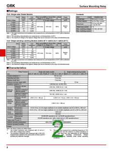
■Approved Standards
UL recognized:
CSA certified:
UL1950 (File No. E41515)
C22.2 No. 950 (File No. LR31928)
BSI (EN60950) (File No.9054)
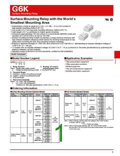
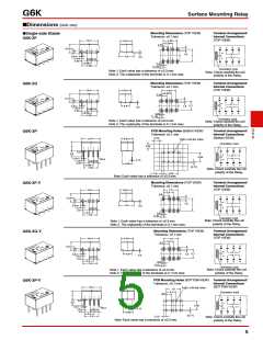
Contact form
DPDT (2c)
Isolation category
Basic Insulation
Voltage
Number of
test
operations
125 VAC
Contact
form
Coil rating
Contact rating
1 A, 30 VDC at 40°C
0.5 A, 60 VDC at 40°C
0.3 A, 125 VAC at 40°C
DPDT G6K-2G(F/P): 3 to 24 VDC
6,000
(2c)
G6K(U)-2G(F/P)-Y: 3 to 24 VDC
■Precautions
●Please refer to “PCB Relays Common Precautions” for correct use.
Correct Use
●Long-term Continuously ON Contacts
●Maximum Allowable Voltage
• Using the Relay in a circuit where the Relay will be ON
continuously for long periods (without switching) can lead to
unstable contacts because the heat generated by the coil itself
will affect the insulation, causing a film to develop on the
contact surfaces. We recommend using a latching relay
(magnetic-holding relay) in this kind of circuit. If a single-side
stable model must be used in this kind of circuit, we
recommend using a fail-safe circuit design that provides
protection against contact failure or coil burnout.
• The maximum allowable voltage of the coil can be obtained
from the coil temperature increase and the heat-resisting
temperature of coil insulating sheath material. (Exceeding the
heat-resisting temperature may result in burning or
short-circuiting.) The maximum allowable voltage also involves
important restrictions which include the following:
• Must not cause thermal changes in or deterioration of the
insulating material.
G
6
K
• Must not cause damage to other control devices.
• Must not cause any harmful effect on people.
• Must not cause fire.
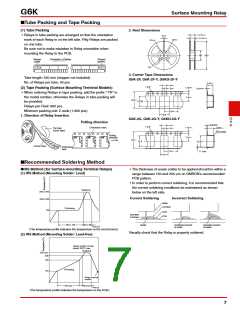
●Relay Handling
• Use the Relay as soon as possible after opening the
moistureproof package. If the Relay is left for a long time after
opening the moisture-proof package, the appearance may
suffer and seal failure may occur after the solder mounting
process. To store the Relay after opening the moisture-proof
package, place it into the original package and sealed the
package with adhesive tape.
• When washing the product after soldering the Relay to a PCB,
use a water-based solvent or alcohol-based solvent, and keep
the solvent temperature to less than 40°C. Do not put the
Therefore, be sure to use the maximum allowable voltage
beyond the value specified in the catalog.
• As a rule, the rated voltage must be applied to the coil. A
voltage exceeding the rated value, however, can be applied to
the coil provided that the voltage is less than the maximum
allowable voltage. It must be noted that continuous voltage
application to the coil will cause a coil temperature increase
thus affecting characteristics such as electrical life and
resulting in the deterioration of coil insulation.
Relay in a cold cleaning bath immediately after soldering.
●Coating
• The Relay mounted on the PCB may be coated or washed but
do not apply silicone coating or detergent containing silicone,
otherwise the silicone coating or detergent may remain on the
surface of the Relay.
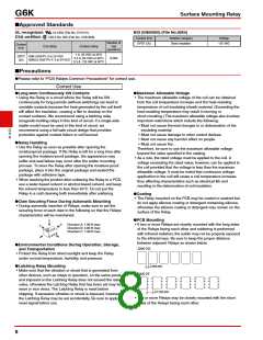
●Claw Securing Force During Automatic Mounting
• During automatic insertion of Relays, make sure to set the
securing force of each claw to the following so that the Relays
characteristics will be maintained.
C
●PCB Mounting
B
• If two or more Relays are closely mounted with the long sides
of the Relays facing each other and soldering is performed
with infrared radiation, the solder may not be properly exposed
to the infrared rays. Be sure to keep the proper distance
between adjacent Relays as shown below.
Direction A: 1.96 N max.
Direction B: 4.90 N max.
Direction C: 1.96 N max.
A
●Environmental Conditions During Operation, Storage,
and Transportation
G6K-2G
• Protect the Relay from direct sunlight and keep the Relay
under normal temperature, humidity, and pressure.
2 mm min.
●Latching Relay Mounting
• Make sure that the vibration or shock that is generated from
other devices, such as relays in operation, on the same panel
and imposed on the Latching Relay does not exceed the rated
value, otherwise the Latching Relay that has been set may be
reset or vice versa. The Latching Relay is reset before
shipping. If excessive vibration or shock is imposed, however,
the Latching Relay may be set accidentally. Be sure to apply a
reset signal before use.
G6K-2F
2.7 mm min.
• Two or more Relays may be closely mounted with the short
sides of the Relays facing each other.
8

 OMRON [ OMRON ELECTRONICS LLC ]