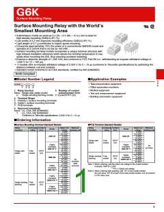
G6K
Surface Mounting Relay
■Ratings
Coil: Single-side Stable Models
Contacts
Must operate Must release Max. voltage
Item
Load
Resistive load
Bifurcated crossbar
Ag (Au-Alloy contact)
Item
Rated
current
(mA)
Coil
resistance
(Ω)
Power
consumption
(mW)
voltage (V) voltage (V)
(V)
Contact type
Contact material
Rated voltage
% of rated voltage
3 VDC
4.5 VDC
5 VDC
33.ꢀ
23.2
21.1
9.1
91
194
ꢀ.3 A at 125 VAC,
1 A at 3ꢀ VDC
Rated load
Approx.
1ꢀꢀ
237
8ꢀ% max.
1ꢀ% min.
15ꢀ%
Rated carry current
1 A
12 VDC
24 VDC
1,315
5,22ꢀ
Max. switching voltage 125 VAC, 6ꢀ VDC
Max. switching current 1 A
4.6
Note 1. The rated current and coil resistance are measured at a coil temperature of 23°C with a tolerance
of ±1ꢀ%.
Note 2. The operating characteristics are measured at a coil temperature of 23°C.
Note 3. The maximum voltage is the highest voltage that can be imposed on the relay coil instantaneously.
Coil: Single-winding Latching Models (G6KU-2F-Y, G6KU-2G-Y, G6KU-2P-Y)
Must operate Must release Max. voltage
Item
Rated
current
(mA)
Coil
resistance
(Ω)
Power
consumption
(mW)
voltage (V) voltage (V)
(V)
Rated voltage
% of rated voltage
3 VDC
4.5 VDC
5 VDC
33.ꢀ
23.2
21.1
9.1
91
194
Approx.
1ꢀꢀ
237
75% max.
75% max.
15ꢀ%
12 VDC
24 VDC
1,315
5,22ꢀ
4.6
G
6
K
Note 1. The rated current and coil resistance are measured at a coil temperature of 23°C with a tolerance
of ±1ꢀ%.
Note 2. The operating characteristics are measured at a coil temperature of 23°C.
Note 3. The maximum voltage is the highest voltage that can be imposed on the relay coil instantaneously.
■Characteristics
Relay Function
Single-side stable models
Single-winding latching models
Item
G6K-2F, G6K-2G, G6K-2P G6K-2F-Y, G6K-2G-Y, G6K-2P-Y G6KU-2F-Y, G6KU-2G-Y, G6KU-2P-Y
Contact resistance *1
Operating (set) time
1ꢀꢀ mΩ max.
3 ms max.
3 ms max.
Release (reset) time
Minimum set/reset signal width
Insulation resistance *2
−
1ꢀ ms
1,ꢀꢀꢀ MΩ min. (at 5ꢀꢀ VDC)
Between coil and
contacts
1,5ꢀꢀ VAC, 5ꢀ/6ꢀ Hz for 1 min
Dielectric
strength
Betweencontactsof
different polarity
1,ꢀꢀꢀ VAC, 5ꢀ/6ꢀ Hz for 1 min
75ꢀ VAC, 5ꢀ/6ꢀ Hz for 1 min
Betweencontactsof
the same polarity
Between coil and
contacts
1,5ꢀꢀ V (1ꢀ × 16ꢀ μs)
2,5ꢀꢀ V (2 × 1ꢀ μs), 1,5ꢀꢀ V (1ꢀ × 16ꢀ μs)
1,5ꢀꢀ V (1ꢀ × 16ꢀ μs)
Impulse
withstand
voltage
Betweencontactsof
different polarity
Betweencontactsof
the same polarity
Destruction
Malfunction
Destruction
Malfunction
Mechanical
Electrical
1ꢀ-55-1ꢀ Hz, 2.5 mm single amplitude (5 mm double amplitude) and 55 to 5ꢀꢀ Hz, 3ꢀꢀ m/s2
1ꢀ-55-1ꢀ Hz, 1.65 mm single amplitude (3.3 mm double amplitude) and 55 to 5ꢀꢀ Hz, 2ꢀꢀ m/s2
Vibration
resistance
1,ꢀꢀꢀ m/s2
Shock
resistance
75ꢀ m/s2
5ꢀ,ꢀꢀꢀ,ꢀꢀꢀ operations min. (at 36,ꢀꢀꢀ operations/hour)
1ꢀꢀ,ꢀꢀꢀ operations min. (with a rated load at 1,8ꢀꢀ operations/hour)
1ꢀ μA at 1ꢀ mVDC
Durability
Failure rate (P level) *3
Ambient operating temperature
Ambient operating humidity
Weight
-4ꢀ to 7ꢀ°C (with no icing or condensation)
5% to 85%
Approx. ꢀ.7 g
Note: The above values are initial values.
*1. The contact resistance was measured with 1ꢀ mA at 1
VDC with a voltage-drop method.
*2. The insulation resistance was measured with a 5ꢀꢀ VDC
megohmmeter applied to the same parts as those used for
checking the dielectric strength.
*3. This value was measured at a switching frequency of 12ꢀ
operations/min and the criterion of contact resistance is
5ꢀ Ω. This value may vary depending on the switching
frequency
and
operating
environment.
Always
double-check relay suitability under actual operating
conditions.
2

 OMRON [ OMRON ELECTRONICS LLC ]