G6K
Surface Mounting Relay
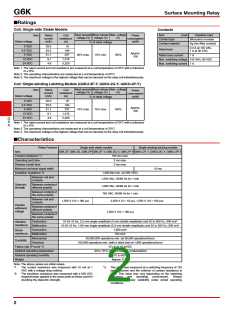
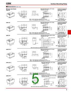
■Tube Packing and Tape Packing
2. Reel Dimensions
(1) Tube Packing
1.0
17.5
• Relays in tube packing are arranged so that the orientation
mark of each Relay in on the left side. Fifty Relays are packed
on one tube.
0.5
2
1.0
21.5
0.2
13
0.5
21
Be sure not to make mistakes in Relay orientation when
mounting the Relay to the PCB.
80 330
Stopper
(gray)
Orientation of Relays
Stopper
(green)
R1
3. Carrier Tape Dimensions
Tube length: 520 mm (stopper not included)
No. of Relays per tube: 50 pcs
G6K-2F, G6K-2F-Y, G6KU-2F-Y
0.1
5.6
0.1
4
+0.1
1.5
0.1
−0
1.75
7.5
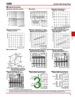
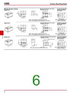
(2) Tape Packing (Surface Mounting Terminal Models)
• When ordering Relays in tape packing, add the prefix “-TR” to
the model number, otherwise the Relays in tube packing will
be provided.
0.1
0.05
2
0.4
0.1
0.1 10.35
16
Relays per Reel: 900 pcs
Minimum packing unit: 2 reels (1,800 pcs)
1. Direction of Relay Insertion
0.1
12
8.6
G
6
K
G6K-2G, G6K-2G-Y, G6KU-2G-Y
Pulling direction
0.05
0.4
0.1
4
+0.1
1.5
0.1
0.1
−0
Orientation mark
Top tape
(cover tape)
1.75
7.5
5.8
0.1
2
R0.3 max.
Pulling
direction
0.1
0.1
16
10.6
0.1
10.6
Carrier tape
Embossed
tape
0.1
12
3° max.
6.9
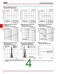
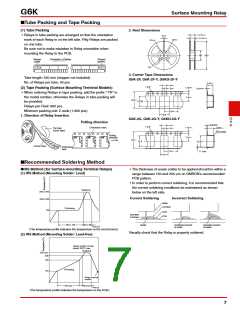
■Recommended Soldering Method
• The thickness of cream solder to be applied should be within a
range between 150 and 200 μm on OMRON’s recommended
PCB pattern.
●IRS Method (for Surface-mounting Terminal Relays)
(1) IRS Method (Mounting Solder: Lead)
• In order to perform correct soldering, it is recommended that
the correct soldering conditions be maintained as shown
below on the left side.
Soldering
220 to 245
Correct Soldering
Incorrect Soldering
180 to 200
Relay
Terminal
Preheating
150
Land
PCB
Heel fillet
is formed
90 to 120
20 to 30
Solder
Insufficient amount
of solder
Excessive amount
of solder
Time (s)
(The temperature profile indicates the temperature on the circuit board.)
Visually check that the Relay is properly soldered.
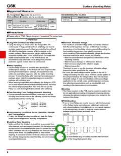
(2) IRS Method (Mounting Solder: Lead-free)
Uppwe surface of case
(peak): 255°C max.
Soldering
250 max.
230
180
Preheating
150
Relay terminal
section
120 max.
30 max.
Time (s)
(The temperature profile indicates the temperature on the PCB.)
7

 OMRON [ OMRON ELECTRONICS LLC ]