G6K
Surface Mounting Relay
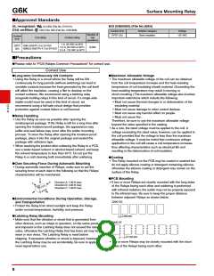
■Engineering Data
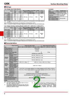
●Maximum Switching Capacity
●Durability
●Ambient Temperature vs.
Maximum Coil Voltage
10
7
1,000
250
500
300
5
200
3
30 VDC resistive load
Ambient temperature: 23°C
Switching frequency:
100
150
100
50
30
1,800 operations/hour
1
0.7
0.5
AC resistive load
10
DC resistive load
125 VAC resistive load
Ambient temperature: 23°C
Switching frequency:
0.3
5
3
50
0
1,800 operations/hour
1
0.1
10
0
0.2
0.4
0.6
0.8
1
1.2
30
50 70 100
300 500 700 1,000
Switching voltage (V)
−40
−20
0
20
40
60
80 100
Switching current (A)
Ambient temperature (°C)
Note: The maximum coil voltage refers to the maximum
value in a varying range of operating power
voltage, not a continuous voltage.
●Ambient Temperature vs.
Switching Current
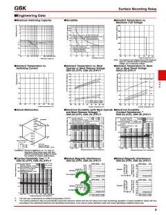
●Ambient Temperature vs. Must
Operate or Must Release Voltage
G6K-2G (F/P), G6K-2G (F/P)-Y
●Ambient Temperature vs. Must
Set or Must Reset Voltage
G6KU-2G (F/P)-Y
1.2
1
100
100
90
90
Max. estimated value
max.
80
70
−
X
min.
80
G
6
K
0.8
0.6
0.4
60
50
40
70
max.
−
X
60
50
40
30
min.
max.
−
30
20
X
min.
0.2
0
Must operate voltage
Must release voltage
10
0
−40
−20
0
20
40
60
80 100
−60
−40 −20
0
20
40
60
80 100
−60
−40 −20
0
20
40
60
80 100
Ambient temperature (°C)
Ambient temperature (°C)
Ambient temperature (°C)
●Shock Malfunction
●Electrical Durability (with Must Operate ●Electrical Durability
and Must Release Voltage) *1
G6K-2G (F/P), G6K-2G (F/P)-Y
(Contact Resistance) *1
G6K-2G (F/P), G6K-2G (F/P)-Y
Y
100
1,000
Sample: G6K-2G
1,000
Sample: G6K-2G
NO contact
NC contact
Energized
Number of Relays: 10 pcs
Number of Relays: 10 pcs
Test conditions: 1 A resistive load
at 30 VDC with an operation rate
of 50%
Switching frequency: 1,800
operations/h
Test conditions: 1 A resistive load at 30 VDC
800
500
300
with an operation rate of 50%
80
Switching frequency: 1,800 operations/h
600
400
200
De-
energized
X
1,000
Z
1,000
max.
min.
60
40
Must operate voltage
100
200
400
600
800
max.
max.
Contact resistance
1,000
Z'
1,000
X'
50
30
min.
min.
max.
min.
Shock directions
X
20
0
X'
Must release voltage
Unit: m/s2
Y
1,000
Z
Y'
Sample: G6K-2G
10
Z'
Number of Relays: 10 pcs
0.001 0.01
0.1
1
10
100
0.001 0.01
0.1
1
10
100
Y'
Operating frequency (x103 operations)
Operating frequency (x103 operations)
Conditions: Shock is applied in ±X, ±Y, and ±±
directions three times each with and
without energizing the Relays to check
the number of contact malfunctions.
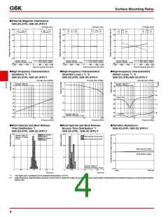
●Contact Reliability Test *1, *2
●Mutual Magnetic Interference
●Mutual Magnetic Interference
G6K-2G (F/P), G6K-2G (F/P)-Y
G6K-2G (F/P), G6K-2G (F/P)-Y
G6K-2G (F/P), G6K-2G (F/P)-Y
1,000
Initial stage Test
Initial stage Test
Sample: G6K-2G
+30
+20
NO contact
+30
+20
max.
Number of Relays: 10 pcs
Test conditions: 10 μA resistive
load at 10 m VDC with an
operation rate of 50%
NC contact
500
300
min.
+10
+10
0
Sample
Sample
0
−10
−20
Switching frequency: 7,200
operations/h
−10
−20
−30
De-energized
De-energized
Average value
Average value
−30
100
Initial stage Test
Initial stage Test
+30
+20
+30
+20
max.
max.
min.
min.
50
30
+10
0
+10
0
Sample
Sample
−10
−20
−30
−10
−20
−30
Energized
Average value
Energized
Average value
10
Must operate voltage
Must release voltage
0.001 0.01 0.1
1
10
100 1,000 10,000 100,000
Must operate voltage
Must release voltage
Operating frequency (x103 operations)
*1. The test was conducted at an ambient temperature of 23°C.
*2. The contact resistance data are periodically measured reference values and are not values from each monitoring operation. Contact resistance values will vary
according to the switching frequency and operating environment, so be sure to check operation under the actual operating conditions before use.
3

 OMRON [ OMRON ELECTRONICS LLC ]