Philips Semiconductors
Product specification
Economy Autosync Deflection Controller
(EASDC)
TDA4858
Application hint: VSCOR is a current input at 5 V.
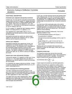
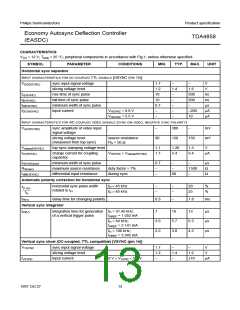
Table 2 Calculation of fosc(V) total spread
Superimposed on this level is a very small positive-going
vertical sawtooth, intended to modulate an external
long-tailed transistor pair. This enables further optional DC
controls of functions which are not directly accessible such
as vertical tilt or vertical linearity (see Fig.17).
Contributing elements
Minimum frequency offset between fosc(V)
and lowest trigger frequency
±10%
Spread of IC
Spread of RVREF
Spread of CVCAP
Total
±3%
±1%
±5%
19%
EW parabola (including horizontal size and trapezium
correction)
EWDRV (pin 11) provides a complete EW drive waveform.
EW parabola amplitude, DC shift (horizontal size) and
trapezium correction can be controlled via separate DC
inputs.
Result for 50 to 110 Hz application:
50 Hz
fosc (V)
=
= 42 Hz
---------------
1.19
EWPAR (pin 21) is used to adjust the parabola amplitude.
This can be a combination of a DC adjustment and a
dynamic waveform modulation.
Application hint: VAGC (pin 22) has a high input
impedance during scan, thus the pin must not be loaded
externally. Otherwise non-linearities in the vertical output
currents may occur due to the changing charge current
during scan.
The EW parabola amplitude also tracks with vertical
picture size. The parabola waveform itself tracks with the
adjustment for vertical picture shift (VPOS).
Application hint: The full vertical sync range of 1 : 2.5 can
be made usable by incorporating an adjustment of the
free-running frequency. Also the complete sync range can
be shifted to higher frequencies (e.g. 70 to 160 Hz) by
EWWID (pin 32) offers two modes of operation:
1. Mode 1
Horizontal size is DC controlled via EWWID (pin 32)
and causes a DC shift at the EWDRV output. Also the
complete waveform is multiplied internally by a signal
proportional to the line frequency (which is detected
via the current at HREF (pin 28). This mode is to be
used for driving EW modulator stages which require a
voltage proportional to the line frequency.
reducing the value of CVCAP
.
Adjustment of vertical size, vertical shift and
S-correction
VPOS (pin 17) is the input for the DC adjustable vertical
picture shift. This pin provides a phase shift at the
sawtooth output VOUT1 and VOUT2 (pins 13 and 12) and
the EW drive output EWDRV (pin 11) in such a way, that
the whole picture moves vertically while maintaining the
correct geometry.
2. Mode 2
EWWID (pin 32) is grounded. Then EWDRV is no
longer multiplied by the line frequency. The DC
adjustment for horizontal size must be added to the
input of the B+ control amplifier BIN (pin 5). This mode
is to be used for driving EW modulators which require
a voltage independent of the line frequency.
The amplitude of the differential output currents at VOUT1
and VOUT2 can be adjusted via input VAMP (pin 18). This
can be a combination of a DC adjustment and a dynamic
waveform modulation.
EWTRP (pin 20) is used to adjust the amount of trapezium
correction in the EW drive waveform.
VSCOR (pin 19) is used to adjust the amount of vertical
S-correction in the output signal.
Application hint: EWTRP (pin 20) is a current input at
5 V. Superimposed on this level is a very small vertical
parabola with positive tips, intended to modulate an
external long-tailed transistor pair. This enables further
optional DC controls of functions which are not directly
accessible such as EW-corner, vertical focus or EW pin
balance (see Fig.17).
The adjustments for vertical size and vertical shift also
affect the waveforms of the EW parabola and the vertical
S-correction. The result of this interaction is that no
readjustment of these parameters is necessary after an
adjustment of vertical picture size or position.
Application hint: VPOS is a current input, which provides
an internal reference voltage while IVPOS is in the specified
adjustment current range. By grounding VPOS (pin 17) the
symmetrical control range is forced to its centre value.
Application hint: By grounding EWTRP (pin 20) the
symmetrical control range is forced to its centre value.
1997 Oct 27
9

 NXP [ NXP ]