®
Numonyx™ StrataFlash Embedded Memory (J3-65nm)
14.0
Electrical characteristics
14.1
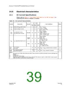
DC Current Specifications
Please refer to Figure 6, “Chip Enable Truth Table for 256-Mb” on page 15 to
understand the device is disable or enabled.
Table 19: DC Current Characteristics
2.7 - 3.6V
Max Unit
Symbol
Parameter
Density
Test Conditions
Notes
Typ
I
Input and V
Load Current
—
± 1
± 1
V
V
V
= V
LI
PEN
CC
CCMAX
µA
µA
= V
1
CCQ
CCQMAX
I
Output Leakage Current
—
LO
= V
or V
SS
IN
CCQ
V
V
= V
CCMAX
= V
CC
CCQ
CCQMAX
CCQ
I
I
V
V
Standby Current,
Power-Down Current
CCS,
CC
CC
CE# = V
RP# = V
RP# = V (for I
256-Mbit
65
210
31
1,2,3
CCD
(for I
)
CCS
)
CCD
CCQ
SS
V
= V
CCMAX
CC
CE# = V
IL
IH
IH
Single
Word
OE# = V
Inputs: V or V
f = 5MHz (1 CLK)
26
mA
mA
1
IL
I
V
Page Mode Read Current
CCR
CC
V
= V
CC
CCMAX
IL
IH
IH
CE# = V
OE# = V
Inputs: V or V
f = 13MHz (17 CLK)
Page
12
35
16
50
IL
I
I
V
V
Program,
Erase
CCW,
CCE
CC
CC
mA
V
= V , program/erase in progress
1,3
1,4
PEN
PENH
I
I
V
V
Program Suspend
Erase Suspend
Refer to
CCS
CCWS
CCES
CC
CC
µA
CE# = V
, suspend in progress
CCQ
I
Notes:
1.
All currents are in RMS unless otherwise noted. These currents are valid for all product versions (packages and
speeds).
2.
3.
4.
Includes STS.
Sampled, not 100% tested.
I
and I
are specified with the device selected. If the device is read or written while in erase suspend
CCWS
CCES
mode, the device’s current draw is I
and I
.
CCR
CCWS
December 2008
319942-02
Datasheet
39

 NUMONYX [ NUMONYX B.V ]