Numonyx™ Wireless Flash Memory (W18)
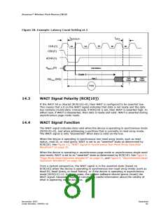
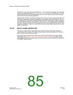
Figure 38: Example: Latency Count Setting at 3
tADD-DELAY
tDATA
2rd
0st
1nd
3th
4th
CLK (C)
CE# (E)
ADV# (V)
AMAX-0 (A)
Valid Address
High Z
Code 3
Valid
Output
Valid
Output
DQ15-0 (D/Q)
R103
14.3
14.4
WAIT Signal Polarity (RCR[10])
If the WAIT bit is cleared (RCR[10]=0), then WAIT is configured to be asserted low.
This means that a 0 on the WAIT signal indicates that data is not ready and the data
bus contains invalid data. Conversely, if RCR[10] is set, then WAIT is asserted high. In
either case, if WAIT is deasserted, then data is ready and valid. WAIT is asserted during
asynchronous page mode reads.
WAIT Signal Function
The WAIT signal indicates data valid when the device is operating in synchronous mode
(RCR[15]=0), and when addressing a partition that is currently in read-array mode.
The WAIT signal is only “deasserted” when data is valid on the bus.
When the device is operating in synchronous non-read-array mode, such as read
status, read ID, or read query, WAIT is set to an “asserted” state as determined by
RCR[10]. See Figure 12, “WAIT Signal in Synchronous Non-Read Array Operation
Waveform” on page 35.
When the device is operating in asynchronous page mode or asynchronous single word
read mode, WAIT is set to an “asserted” state as determined by RCR[10]. See Figure 8,
“Page-Mode Read Operation Waveform” on page 31, and Figure 6, “Asynchronous Read
Operation Waveform” on page 29.
From a system perspective, the WAIT signal is in the asserted state (based on
RCR[10]) when the device is operating in synchronous non-read-array mode (such as
Read ID, Read Query, or Read Status), or if the device is operating in asynchronous
mode (RCR[15]=1). In these cases, the system software should ignore (mask) the
WAIT signal, because it does not convey any useful information about the validity of
what is appearing on the data bus.
November 2007
Order Number: 290701-18
Datasheet
81

 NUMONYX [ NUMONYX B.V ]