Status Register
M29FxxxFT, M29FxxxFB
5
Status Register
Bus Read operations from any address always read the Status Register during Program
and Erase operations. It is also read during Erase Suspend when an address within a block
being erased is accessed.
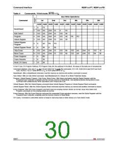
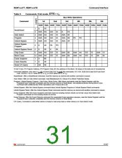
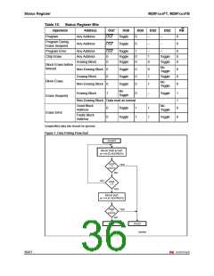
The bits in the Status Register are summarized in Table 10.: Status Register Bits.
5.1
Data Polling Bit
The Data Polling Bit (DQ7) can be used to identify whether the Program/Erase Controller
has successfully completed its operation or if it has responded to an Erase Suspend. The
Data Polling Bit is output on DQ7 when the Status Register is read.
During Program operations the Data Polling Bit outputs the complement of the bit being
programmed to DQ7. After successful completion of the Program operation the memory
returns to Read mode and Bus Read operations from the address just programmed output
DQ7, not its complement.
During Erase operations the Data Polling Bit outputs ’0’, the complement of the erased state
of DQ7. After successful completion of the Erase operation the memory returns to Read
Mode.
In Erase Suspend mode the Data Polling Bit will output a ’1’ during a Bus Read operation
within a block being erased. The Data Polling Bit will change from a ’0’ to a ’1’ when the
Program/Erase Controller has suspended the Erase operation.
Figure 1. Data Polling Flowchart, gives an example of how to use the Data Polling Bit. A
Valid Address is the address being programmed or an address within the block being
erased.
5.2
Toggle Bit
The Toggle Bit (DQ6) can be used to identify whether the Program/Erase Controller has
successfully completed its operation or if it has responded to an Erase Suspend. The Toggle
Bit is output on DQ6 when the Status Register is read.
During Program and Erase operations the Toggle Bit changes from ’0’ to ’1’ to ’0’, etc., with
successive Bus Read operations at any address. After successful completion of the
operation the memory returns to Read mode.
During Erase Suspend mode the Toggle Bit will output when addressing a cell within a block
being erased. The Toggle Bit will stop toggling when the Program/Erase Controller has
suspended the Erase operation.
If any attempt is made to erase a protected block, the operation is aborted, no error is
signalled and DQ6 toggles for approximately 100µs. If any attempt is made to program a
protected block or a suspended block, the operation is aborted, no error is signalled and
DQ6 toggles for approximately 1µs.
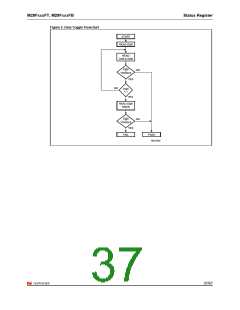
Figure 2. Data Toggle Flowchart, gives an example of how to use the Data Toggle Bit.
34/67

 NUMONYX [ NUMONYX B.V ]