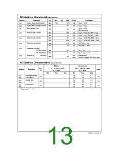
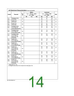
AC Electrical Characteristics Scan Test Operation
Military
Commercial
e b
a
e b
A
a
V
*
T
55 C to 125 C
§
T
40 C to 85 C
§
CC
§
§
A
Symbol
Parameter
Units
e
e
(V)
C
50 pF
C
L
50 pF
L
Min
Typ
Max
Min
Typ
Max
t
t
Propagation Delay
TCK to TDO
2.9
4.2
6.1
7.7
10.2
12.1
PLH
5.0
5.0
5.0
ns
ns
ns
ns
PHL
t
t
Disable Time
TCK to TDO
2.1
3.3
5.9
7.4
10.7
12.5
PLZ
PHZ
t
t
Enable Time
TCK to TDO
4.6
2.8
8.7
6.8
13.7
11.5
PZL
PZH
t
t
Propagation Delay
TCK to Data Out
2.8
4.5
6.3
8.2
10.7
13.0
PLH
5.0
5.0
PHL
during Update-DR State
t
t
Propagation Delay
TCK to Data Out
3.3
5.0
7.2
9.3
12.2
14.8
PLH
ns
ns
PHL
during Update-IR State
t
t
Propagation Delay
TCK to Data Out
during Test Logic
Reset State
3.7
5.7
8.4
14.0
17.2
PLH
10.8
PHL
5.0
t
t
Disable Time
2.8
3.5
7.6
8.4
13.9
14.5
PLZ
ns
ns
ns
TCK to Data Out
during Update-DR State
5.0
5.0
PHZ
t
t
Disable Time
3.6
3.8
8.7
9.2
15.1
15.9
PLZ
TCK to Data Out
during Update-IR State
PHZ
t
t
Disable Time
4.0
4.2
9.8
9.9
17.1
16.6
PLZ
TCK to Data Out
during Test Logic
Reset State
PHZ
5.0
t
t
Enable Time
4.4
3.0
9.3
7.5
15.5
13.3
PZL
ns
ns
ns
TCK to Data Out
during Update-DR State
5.0
5.0
PZH
t
t
Enable Time
5.2
3.9
10.7
9.0
17.4
15.4
PZL
TCK to Data Out
during Update-IR State
PZH
t
t
Enable Time
5.7
3.0
12.0
10.2
19.8
17.6
PZL
TCK to Data Out
during Test Logic
Reset State
PZH
5.0
g
*Voltage Range 5.0V 0.5V
All Propagation Delays involving TCK are measured from the falling edge of TCK.
http://www.national.com
14

 NSC [ National Semiconductor ]