negative signal differs by only 0.5 dB worst case. Substitut-
Application Hints (Continued)
%
ing 5 resistors increases this to 2 dB worst case. (A 2 dB
±
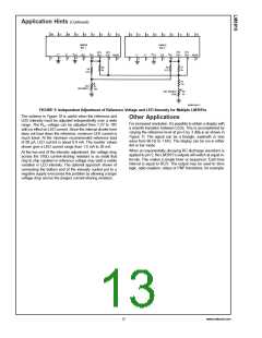
Power dissipation, especially in bar mode should be given
consideration. For example, with a 5V supply and all LEDs
programmed to 20 mA the driver will dissipate over 600 mW.
In this case a 7.5Ω resistor in series with the LED supply will
cut device heating in half. The negative end of the resistor
should be bypassed with a 2.2 µF solid tantalum capacitor to
pin 2.
gain difference means that the display may have a 1 dB er-
ror when the input is a nonsymmetrical transient). The aver-
aging time constant is R5–C2. A simple modification results
in the precision full-wave detector of Figure 4. Since the filter
capacitor is not buffered, this circuit can drive only high im-
pedance loads such as the input of an LM3915.
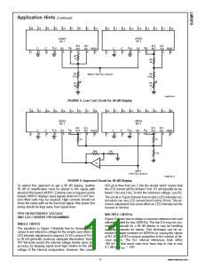
TIPS ON RECTIFIER CIRCUITS
The simplest way to display an AC signal using the LM3915
is to apply it right to pin 5 unrectified. Since the LED illumi-
nated represents the instantaneous value of the AC wave-
form, one can readily discern both peak and average values
of audio signals in this manner. The LM3915 will respond to
positive half-cycles only but will not be damaged by signals
±
±
up to 35V (or up to 100V if a 39k resistor is in series with
the input). It’s recommended to use dot mode and to run the
LEDs at 30 mA for high enough average intensity.
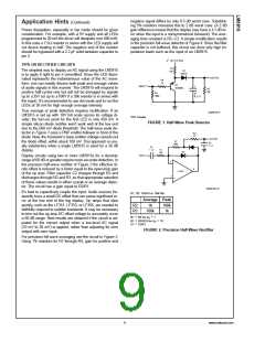
True average or peak detection requires rectification. If an
LM3915 is set up with 10V full scale across its voltage di-
vider, the turn-on point for the first LED is only 450 mV. A
simple silicon diode rectifier won’t work well at the low end
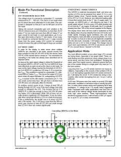
due to the 600 mV diode threshold. The half-wave peak de-
tector in Figure 1 uses a PNP emitter-follower in front of the
diode. Now, the transistor’s base-emitter voltage cancels out
the diode offset, within about 100 mV. This approach is usu-
ally satisfactory when a single LM3915 is used for a 30 dB
display.
DS005104-9
*
DC Couple
FIGURE 1. Half-Wave Peak Detector
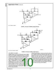
Display circuits using two or more LM3915s for a dynamic
range of 60 dB or greater require more accurate detection. In
the precision half-wave rectifier of Figure 2 the effective di-
ode offset is reduced by a factor equal to the open-loop gain
of the op amp. Filter capacitor C2 charges through R3 and
discharges through R2 and R3, so that appropriate selection
of these values results in either a peak or an average detec-
tor. The circuit has a gain equal to R2/R1.
DS005104-10
It’s best to capacitively couple the input. Audio sources fre-
quently have a small DC offset that can cause significant er-
ror at the low end of the log display. Op amps that slew
quickly, such as the LF351, LF353, or LF356, are needed to
faithfully respond to sudden transients. It may be necessary
to trim out the op amp DC offset voltage to accurately cover
a 60 dB range. Best results are obtained if the circuit is ad-
justed for the correct output when a low-level AC signal
(10 mV to 20 mV) is applied, rather than adjusting for zero
output with zero input.
D1, D2: 1N914 or 1N4148
Average Peak
R2
R3
1k
100k
1k
100k
=
=
1
R1 R2 for A
V
=
=
10
R1 R2/R10 for A
V
=
C1 10/R1
FIGURE 2. Precision Half-Wave Rectifier
For precision full-wave averaging use the circuit in Figure 3.
%
Using 1 resistors for R1 through R4, gain for positive and
9
www.national.com

 NSC [ National Semiconductor ]