Application Hints (Continued)
DS005104-17
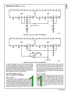
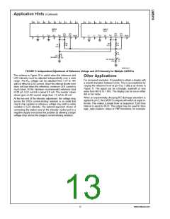
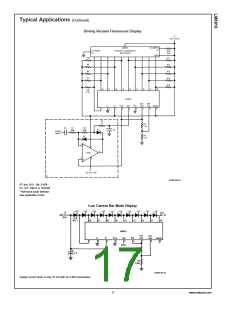
FIGURE 9. Independent Adjustment of Reference Voltage and LED Intensity for Multiple LM3915s
The scheme in Figure 10 is useful when the reference and
LED intensity must be adjusted independently over a wide
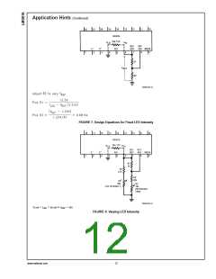
Other Applications
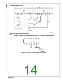
For increased resolution, it’s possible to obtain a display with
range. The RHI voltage can be adjusted from 1.2V to 10V
a smooth transition between LEDs. This is accomplished by
with no effect on LED current. Since the internal divider here
varying the reference level at pin 6 by 3 dBp-p as shown in
does not load down the reference, minimum LED current is
Figure 11. The signal can be a triangle, sawtooth or sine
much lower. At the minimum recommended reference load
wave from 60 Hz to 1 kHz. The display can be run in either
of 80 µA, LED current is about 0.8 mA. The resistor values
dot or bar mode.
shown give a LED current range from 1.5 mA to 20 mA.
When an exponentially decaying RC discharge waveform is
applied to pin 5, the LM3915’s outputs will switch at equal in-
At the low end of the intensity adjustment, the voltage drop
across the 510Ω current-sharing resistors is so small that
tervals. This makes a simple timer or sequencer. Each time
chip to chip variation in reference voltage may yield a visible
interval is equal to RC/3. The output may be used to drive
variation in LED intensity. The optional approach shown of
logic, opto-couplers, relays or PNP transistors, for example.
connecting the bottom end of the intensity control pot to a
negative supply overcomes this problem by allowing a larger
voltage drop across the (larger) current-sharing resistors.
13
www.national.com

 NSC [ National Semiconductor ]