Application Hints (Continued)
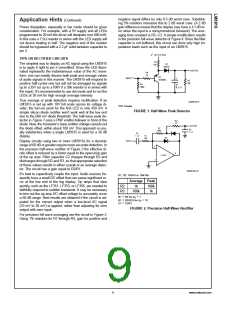
DS005104-11
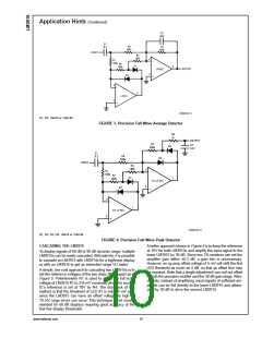
D1, D2: 1N914 or 1N4148
FIGURE 3. Precision Full-Wave Average Detector
DS005104-12
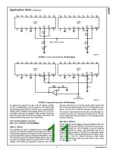
D1, D2, D3, D4: 1N914 or 1N4148
FIGURE 4. Precision Full-Wave Peak Detector
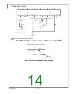
CASCADING THE LM3915
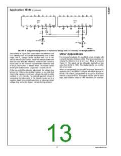
A better approach shown in Figure 6 is to keep the reference
at 10V for both LM3915s and amplify the input signal to the
To display signals of 60 dB or 90 dB dynamic range, multiple
LM3915s can be easily cascaded. Alternatively, it is possible
to cascade an LM3915 with LM3914s for a log/linear display
or with an LM3916 to get an extended range VU meter.
%
lower LM3915 by 30 dB. Since two 1 resistors can set the
±
amplifier gain within 0.2 dB, a gain trim is unnecessary.
However, an op amp offset voltage of 5 mV will shift the first
LED threshold as much as 4 dB, so that an offset trim may
be required. Note that a single adjustment can null out offset
in both the precision rectifier and the 30 dB gain stage. Alter-
natively, instead of amplifying, input signals of sufficient am-
plitude can be fed directly to the lower LM3915 and attenu-
ated by 30 dB to drive the second LM3915.
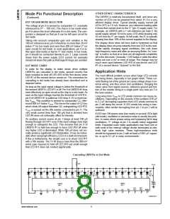
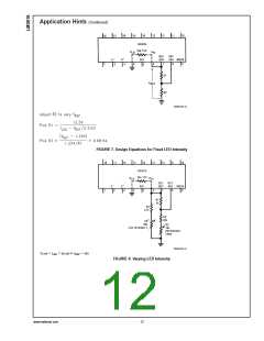
A simple, low cost approach to cascading two LM3915s is to
set the reference voltages of the two chips 30 dB apart as in
Figure 5. Potentiometer R1 is used to adjust the full scale
#
voltage of LM3915 1 to 316 mV nominally while the second
IC’s reference is set at 10V by R4. The drawback of this
method is that the threshold of LED 1 is only 14 mV and,
#
since the LM3915 can have an offset voltage as high as
10 mV, large errors can occur. This technique is not recom-
mended for 60 dB displays requiring good accuracy at the
first few display thresholds.
www.national.com
10

 NSC [ National Semiconductor ]