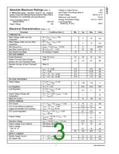
Absolute Maximum Ratings (Note 1)
If Military/Aerospace specified devices are required,
please contact the National Semiconductor Sales Office/
Distributors for availability and specifications.
Voltage on Output Drivers
Input Signal Overvoltage (Note 4)
Divider Voltage
25V
35V
±
−100 mV to V+
Reference Load Current
Storage Temperature Range
10 mA
−55˚C to +150˚C
Power Dissipation (Note 6)
Molded DIP(N)
1365 mW
25V
Lead Temperature
(Soldering, 10 sec.)
260˚C
Supply Voltage
Electrical Characteristics (Notes 2, 4)
Parameter
Conditions (Note 2)
Min
Typ
Max
Units
COMPARATOR
=
0V ≤ VRLO VRHI ≤ 12V,
Offset Voltage, Buffer and First
Comparator
3
3
10
15
mV
mV
=
ILED 1 mA
=
0V ≤ VRLO VRHI ≤ 12V,
Offset Voltage, Buffer and Any Other
Comparator
=
ILED 1 mA
=
=
Gain (∆ILED/∆VIN
)
IL(REF) 2 mA, ILED 10 mA
0V ≤ VIN ≤ (V+ − 1.5V)
No Change in Display
3
8
mA/mV
Input Bias Current (at Pin 5)
Input Signal Overvoltage
VOLTAGE-DIVIDER
25
100
35
nA
V
−35
Divider Resistance
Total, Pin 6 to 4
(Note 3)
16
28
36
kΩ
Relative Accuracy (Input Change
Between Any Two Threshold Points)
2.0
3.0
4.0
dB
Absolute Accuracy at Each Threshold
Point
(Note 3)
VIN = −3, −6 dB
−0.5
−0.5
−0.5
−0.5
+0.5
+0.65
+1.0
dB
dB
dB
dB
VIN = −9 dB
VIN = −12, −15, −18 dB
VIH = −21, −24, −27 dB
+1.5
VOLTAGE REFERENCE
Output Voltage
0.1 mA ≤ IL(REF) ≤ 4 mA,
1.2
1.28
0.01
0.4
1.34
0.03
2
V
V+ VLED 5V
=
=
3V ≤ V+ ≤ 18V
%
/V
Line Regulation
Load Regulation
0.1 mA ≤ IL(REF) ≤ 4 mA,
%
V+ VLED 5V
=
=
=
0˚C ≤ TA ≤ +70˚C, IL(REF) 1 mA,
Output Voltage Change with
Temperature
%
1
+
=
V
VLED 5V
Adjust Pin Current
OUTPUT DRIVERS
LED Current
75
120
µA
+
=
=
=
V
VLED 5V, IL(REF) 1 mA
7
10
0.12
1.2
0.1
1
13
0.4
3
mA
mA
=
VLED = 5V, ILED 2 mA
VLED = 5V, ILED 20 mA
LED Current Difference (Between
Largest and Smallest LED Currents)
LED Current Regulation
2V ≤ VLED ≤ 17V, ILED = 2 mA
ILED = 20 mA
0.25
3
mA
V
=
=
@
Dropout Voltage
ILED(ON) 20 mA, VLED 5V,
∆ILED 2 mA
1.5
=
=
=
Saturation Voltage
ILED 2.0 mA, IL(REF) 0.4 mA
0.15
0.1
0.4
10
V
Output Leakage, Each Collector
(Bar Mode) (Note 5)
µA
Output Leakage
Pins 10–18
(Dot Mode) (Note 5)
0.1
10
µA
µA
Pin 1
60
150
450
SUPPLY CURRENT
V+ +5V, IL(REF) 0.2 mA
V+ +20V, IL(REF) 1.0 mA
2.4
6.1
4.2
9.2
mA
mA
=
=
=
=
Standby Supply Current
(All Outputs Off)
3
www.national.com

 NSC [ National Semiconductor ]