Application Hints (Continued)
THERMAL CONSIDERATIONS
The LM2419 requires that the package be properly heat
sunk under all operating conditions. Maximum ratings re-
quire that the device case temperature be limited to 90 C
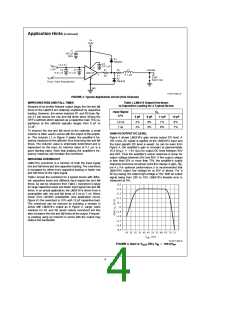
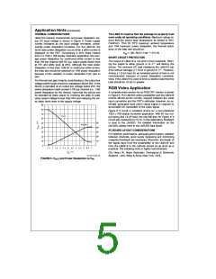
LM2419’s transfer characteristic and power dissipation ver-
sus DC input voltage is shown in Figure 5. Power supply
current increases as the input voltage increases, conse-
quently power dissipation increases. For the LM2419, the
worst case power dissipation occurs when a white screen is
displayed on the CRT. Considering a 20% black retrace
time in a 1024 x 768 display resolution application, the aver-
age power dissipation for continuous white screen is less
§
maximum. Thus for 50 C maximum ambient temperature
§
and 13W maximum power dissipation, the thermal resist-
ance of the heat sink should be:
s
e
3 C/W
i
(90–50) C/13W
§
§
sa
SHORT CIRCUIT PROTECTION
The output of LM2419 is not short circuit protected. Short-
ing the output to either ground or to Va will destroy the
device. The minimum DC load resistance the LM2419 can
drive without damage is 1.6 kX to ground or Va. However,
driving a 1.6 kX load for an extended period of time is not
recommended because of power dissipation considera-
tions. If the LM2419 is used to drive a resistive load then the
load should be 10 kX or greater.
than 4W per channel with 50 V output signal (black level
PP
at 75V and white level at 25V). Although the total power
dissipation is less than 12W for a continuous white screen,
the heat sink should be selected for 13W power dissipation
because of the variation in power dissipation from part to
part.
For thermal and gain linearity considerations, the output low
voltage (white level) should be maintained above 20V. If the
device is operated at an output low voltage below 20V, the
power dissipation might exceed 4.7W per channel (i.e., 14W
power dissipation for the device). Note that the device can
be operated at lower power by reducing the peak to peak
video output voltage to less than 50V and clamping the vid-
eo black level close to the supply voltage.
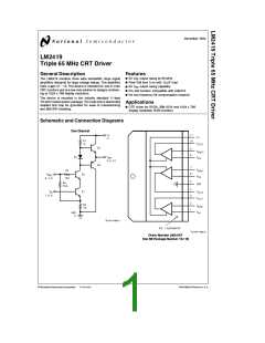
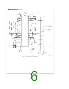
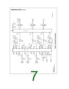
RGB Video Application
A complete video section for an RGB CRT monitor is shown
in Figure 6. The LM1203 video preamplifier and the LM2419
include almost all the circuitry required between the video
input connection and the CRT’s cathodes. However, an ex-
ternally generated back porch clamp signal is required to
accomplish DC restoration of the video signal.
Figure 6 ’s circuit is excellent choice for a non-interlaced
1024 x 768 display resolution application. With 50 V out-
PP
put swing and 12 pF load, the rise/fall time for Figure 6 ’s
circuit was measured at 7.5 ns. In this application, feedback
is local to the LM1203. For detailed information on the
LM1203, please refer to the LM1203 data sheet.
PC BOARD LAYOUT CONSIDERATIONS
For optimum performance, adequate ground plane, isolation
between channels, good supply bypassing and minimizing
unwanted feedback are necessary. Moreover, the length of
the signal trace from the preamplifier to the LM2419 and
from the LM2419 to the cathode should be as short as is
practical. The following book is highly recommended:
Ott, Henry W, Noise Reduction Techniques in Electronic
Systems , John Wiley & Sons, New York, 1976.
TL/H/11442–10
FIGURE 5. V
OUT
and Power Dissipation vs V
IN
5

 NSC [ National Semiconductor ]