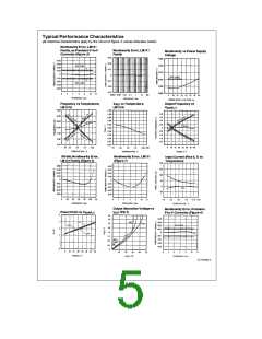
e
Electrical Characteristics T 25 C unless otherwise specified (Note 2) (Continued)
§
A
Parameter
Conditions
Min
Typ
Max
Units
TIMER
c
V
S
Timer Threshold Voltage, Pin 5
0.63
0.667
0.70
e
Input Bias Current, Pin 5
All Devices
V
S
0V
15V
s
s
g
200
200
g
V
9.9V
10
100
1000
500
nA
nA
nA
PIN 5
e
e
LM131/LM231/LM331
LM131A/LM231A/LM331A
V
PIN 5
V
PIN 5
10V
10V
e
V
(Reset)
I
5 mA
0.22
0.5
V
SAT PIN 5
CURRENT SOURCE (Pin 1)
e
e
0
Output Current
R
S
14 kX, V
PIN 1
LM131, LM131A, LM231, LM231A
LM331, LM331A
126
116
135
136
144
156
mA
mA
s
s
Change with Voltage
0V
V
PIN 1
10V
0.2
1.0
mA
Current Source OFF Leakage
LM131, LM131A
0.01
0.02
2.0
1.0
10.0
50.0
nA
nA
nA
LM231, LM231A, LM331, LM331A
All Devices
e
T
A
T
MAX
Operating Range of Current (Typical)
(10 to 500)
mA
REFERENCE VOLTAGE (Pin 2)
LM131, LM131A, LM231, LM231A
LM331, LM331A
1.76
1.70
1.89
1.89
2.02
2.08
V
V
DC
DC
g
Stability vs Temperature
Stability vs Time, 1000 Hours
LOGIC OUTPUT (Pin 3)
60
ppm/ C
§
%
g
0.1
e
e
V
I
I
5 mA
3.2 mA (2 TTL Loads), T
0.15
0.10
0.50
0.40
1.0
V
V
mA
SAT
s
s
T
MAX
T
A
MIN
g
OFF Leakage
0.05
SUPPLY CURRENT
e
e
e
e
LM131, LM131A, LM231,
LM231A
LM331, LM331A
V
S
V
S
V
S
V
S
5V
40V
5V
2.0
2.5
1.5
2.0
3.0
4.0
3.0
4.0
4.0
6.0
6.0
8.0
mA
mA
mA
mA
40V
Note 1: Absolute Maximum Ratings indicate limits beyond which damage to the device may occur. DC and AC electrical specifications do not apply when operating
the device beyond its specified operating conditions.
s
s
40V, unless otherwise noted.
Note 2: All specifications apply in the circuit of Figure 3, with 4.0V
V
S
c
b
Note 3: Nonlinearity is defined as the deviation of f
OUT
from V
IN
over the frequency range 1 Hz to 11 kHz. For the timing capacitor, C , use NPO ceramic, Teflon , or polystyrene.
(10 kHz/ 10 V ) when the circuit has been trimmed for zero error at 10 Hz and at 10 kHz,
DC
É
T
Note 4: Human body model, 100 pF discharged through a 1.5 kX resistor.
3

 NSC [ National Semiconductor ]