Typical Applications (Continued)
For best results, all the components should be stable low-
temperature-coefficient components, such as metal-film re-
sistors. The capacitor should have low dielectric absorption;
depending on the temperature characteristics desired, NPO
ceramic, polystyrene, Teflon or polypropylene are best
suited.
The average current fed into the op amp’s summing point
c
c
/R . In this circuit, the voltage offset of the LM131
(pin 2) is i
b
(1.1 R C )
t
f which is perfectly balanced with
t
V
IN IN
input comparator does not affect the offset or accuracy of
the V-to-F converter as it does in the stand-alone V-to-F
converter; nor does the LM131 bias current or offset cur-
rent. Instead, the offset voltage and offset current of the
operational amplifier are the only limits on how small the
signal can be accurately converted. Since op amps with
voltage offset well below 1 mV and offset currents well be-
low 2 nA are available at low cost, this circuit is recommend-
ed for best accuracy for small signals. This circuit also re-
sponds immediately to any change of input signal (which a
stand-alone circuit does not) so that the output frequency
A capacitor C is added from pin 7 to ground to act as a
IN
filter for V . A value of 0.01 mF to 0.1 mF will be adequate in
IN
most cases; however, in cases where better filtering is re-
quired, a 1 mF capacitor can be used. When the RC time
constants are matched at pin 6 and pin 7, a voltage step at
V
will cause a step change in f
. If C is much less
IN
to stop momentarily.
IN
OUT
OUT
than C , a step at V may cause f
L
IN
A 47X resistor, in series with the 1 mF C , is added to give
L
will be an accurate representation of V , as quickly as 2
IN
output pulses’ spacing can be measured.
hysteresis effect which helps the input comparator provide
the excellent linearity (0.03% typical).
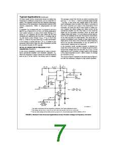
In the precision mode, excellent linearity is obtained be-
cause the current source (pin 1) is always at ground poten-
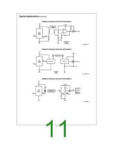
DETAIL OF OPERATION OF PRECISION V-TO-F
CONVERTER (FIGURE 3)
tial and that voltage does not vary with V or f
IN
. (In the
OUT
In this circuit, integration is performed by using a conven-
tional operational amplifier and feedback capacitor, C .
F
stand-alone V-to-F converter, a major cause of non-linearity
is the output impedance at pin 1 which causes i to change
When the integrator’s output crosses the nominal threshold
level at pin 6 of the LM131, the timing cycle is initiated.
as a function of V ).
IN
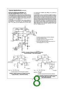
The circuit ofFigure 4 operates in the same way asFigure 3,
but with the necessary changes for high speed operation.
b
V
R
1
IN
S
e
f
#
#
OUT
2.09 V
R
R C
t t
IN
TL/H/5680–5
*Use stable components with low temperature coefficients. See Typical Applications section.
e
e
4.5V to 8V.
**This resistor can be 5 kX or 10 kX for V
8V to 22V, but must be 10 kX for V
S
S
***Use low offset voltage and low offset current op amps for A1: recommended types LM108, LM308A, LF411A
FIGURE 3. Standard Test Circuit and Applications Circuit, Precision Voltage-to-Frequency Converter
7

 NSC [ National Semiconductor ]