The user must set the BUSY flag immediately upon entering
the Slave mode. This ensures that all data bits sent by the
Master is shifted properly. After eight clock pulses the BUSY
flag is clear, the shift clock is stopped, and the sequence
may be repeated.
12.0 MICROWIRE/PLUS (Continued)
12.1.2 MICROWIRE/PLUS Slave Mode Operation
In the MICROWIRE/PLUS Slave mode of operation the SK
clock is generated by an external source. Setting the MSEL
bit in the CNTRL register enables the SO and SK functions
onto the G Port. The SK pin must be selected as an input
and the SO pin is selected as an output pin by setting and re-
setting the appropriate bits in the Port G configuration regis-
ter. Table 11 summarizes the settings required to enter the
Slave mode of operation.
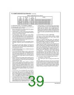
12.1.3 Alternate SK Phase Operation and SK Idle
Polarity
The device allows either the normal SK clock or an alternate
phase SK clock to shift data in and out of the SIO register. In
both the modes the SK idle polarity can be either high or low.
The polarity is selected by bit 5 of Port G data register. In the
normal mode data is shifted in on the rising edge of the SK
clock and the data is shifted out on the falling edge of the SK
clock. In the alternate SK phase operation, data is shifted in
on the falling edge of the SK clock and shifted out on the ris-
ing edge of the SK clock. Bit 6 of Port G configuration regis-
ter selects the SK edge.
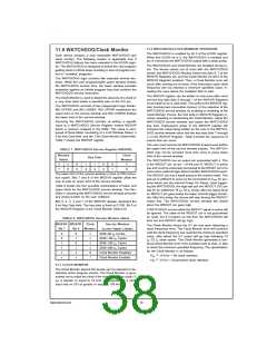
TABLE 11. MICROWIRE/PLUS Mode Settings
This table assumes that the control flag MSEL is set.
G4 (SO)
Config. Bit
1
G5 (SK)
Config. Bit
1
G4
Fun.
SO
G5
Fun.
Int.
Operation
MICROWIRE/PLUS
Master
A control flag, SKSEL, allows either the normal SK clock or
the alternate SK clock to be selected. Resetting SKSEL
causes the MICROWIRE/PLUS logic to be clocked from the
normal SK signal. Setting the SKSEL flag selects the alter-
nate SK clock. The SKSEL is mapped into the G6 configura-
tion bit. The SKSEL flag will power up in the reset condition,
selecting the normal SK signal.
SK
0
1
0
1
0
0
TRI-
STATE
SO
Int.
MICROWIRE/PLUS
Master
SK
Ext. MICROWIRE/PLUS
SK Slave
Ext. MICROWIRE/PLUS
SK Slave
TRI-
STATE
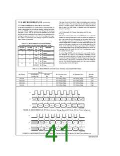
TABLE 12. MICROWIRE/PLUS Shift Clock Polarity and Sample/Shift Phase
Port G
SK Phase
G6 (SKSEL)
G5 Data
SO Clocked Out
On:
SI Sampled On:
SK Idle
Phase
Low
Config. Bit
Bit
0
Normal
Alternate
Alternate
Normal
0
1
0
1
SK Falling Edge
SK Rising Edge
SK Rising Edge
SK Falling Edge
SK Rising Edge
SK Falling Edge
SK Falling Edge
SK Rising Edge
0
Low
1
High
1
High
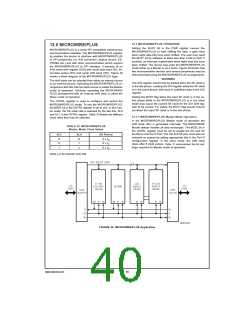
DS101116-33
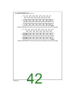
FIGURE 30. MICROWIRE/PLUS SPI Mode Interface Timing, Normal SK Mode, SK Idle Phase being Low
DS101116-34
FIGURE 31. MICROWIRE/PLUS SPI Mode Interface Timing, Alternate SK Mode, SK Idle Phase being Low
41
www.national.com

 NSC [ National Semiconductor ]