12.1 MICROWIRE/PLUS OPERATION
12.0 MICROWIRE/PLUS
Setting the BUSY bit in the PSW register causes the
MICROWIRE/PLUS to start shifting the data. It gets reset
when eight data bits have been shifted. The user may reset
the BUSY bit by software to allow less than 8 bits to shift. If
enabled, an interrupt is generated when eight data bits have
been shifted. The device may enter the MICROWIRE/PLUS
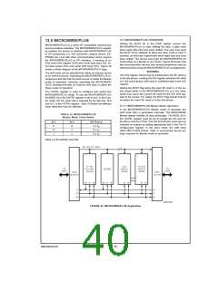
mode either as a Master or as a Slave. Figure 29 shows how
two microcontroller devices and several peripherals may be
interconnected using the MICROWIRE/PLUS arrangements.
MICROWIRE/PLUS is a serial SPI compatible synchronous
communications interface. The MICROWIRE/PLUS capabil-
ity enables the device to interface with MICROWIRE/PLUS
or SPI peripherals (i.e. A/D converters, display drivers, EE-
PROMs etc.) and with other microcontrollers which support
the MICROWIRE/PLUS or SPI interface. It consists of an
8-bit serial shift register (SIO) with serial data input (SI), se-
rial data output (SO) and serial shift clock (SK). Figure 29
shows a block diagram of the MICROWIRE/PLUS logic.
WARNING
The shift clock can be selected from either an internal source
or an external source. Operating the MICROWIRE/PLUS ar-
rangement with the internal clock source is called the Master
mode of operation. Similarly, operating the MICROWIRE/
PLUS arrangement with an external shift clock is called the
Slave mode of operation.
The SIO register should only be loaded when the SK clock is
in the idle phase. Loading the SIO register while the SK clock
is in the active phase, will result in undefined data in the SIO
register.
Setting the BUSY flag when the input SK clock is in the ac-
tive phase while in the MICROWIRE/PLUS is in the slave
mode may cause the current SK clock for the SIO shift reg-
ister to be narrow. For safety, the BUSY flag should only be
set when the input SK clock is in the idle phase.
The CNTRL register is used to configure and control the
MICROWIRE/PLUS mode. To use the MICROWIRE/PLUS,
the MSEL bit in the CNTRL register is set to one. In the mas-
ter mode, the SK clock rate is selected by the two bits, SL0
and SL1, in the CNTRL register. Table 10 details the different
clock rates that may be selected.
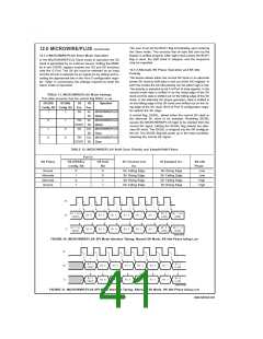
12.1.1 MICROWIRE/PLUS Master Mode Operation
In the MICROWIRE/PLUS Master mode of operation the
shift clock (SK) is generated internally. The MICROWIRE
Master always initiates all data exchanges. The MSEL bit in
the CNTRL register must be set to enable the SO and SK
functions onto the G Port. The SO and SK pins must also be
selected as outputs by setting appropriate bits in the Port G
configuration register. In the slave mode, the shift clock
stops after 8 clock pulses. Table 11 summarizes the bit set-
tings required for Master mode of operation.
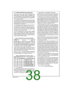
TABLE 10. MICROWIRE/PLUS
Master Mode Clock Select
SL1
0
SL0
SK Period
2 x tC
0
1
x
0
4 x tC
1
8 x tC
Where t is the instruction cycle clock
C
DS101116-32
FIGURE 29. MICROWIRE/PLUS Application
www.national.com
40

 NSC [ National Semiconductor ]