Nexperia
XC7SH86
2-input EXCLUSIVE-OR gate
V
CC
V
V
O
I
PULSE
GENERATOR
DUT
C
50 pF
L
R
T
mna034
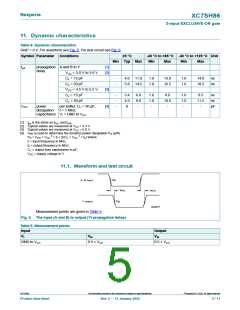
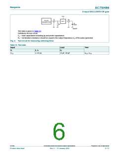
Test data is given in Table 10.
Definitions for test circuit:
CL = load capacitance including jig and probe capacitance;
RT = termination resistance should be equal to the output impedance Zo of the pulse generator.
Fig. 6. Test circuit for measuring switching times
Table 10. Test data
Input
VI
Load
Test
tr, tf
CL
VCC
≤ 3.0 ns
15 pF, 50 pF
tPLH, tPHL
©
XC7SH86
All information provided in this document is subject to legal disclaimers.
Nexperia B.V. 2022. All rights reserved
Product data sheet
Rev. 2 — 11 January 2022
6 / 11

 NEXPERIA [ Nexperia ]