µPD75216A
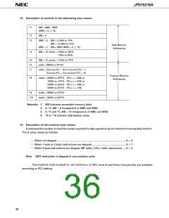
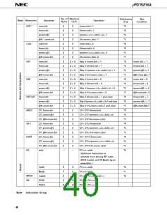
(3) Description of symbols in the addressing area column
*1
MB = MBE • MBS
(MBS = 0, 1, 15)
*2
*3
MB = 0
MBE = 0 : MB = 0 (00H to 7FH)
MB = 15 (80H to FFH)
Data Memory
Addressing
MBE = 1 : MB = MBS (MBS = 0, 1, 15)
*4
MB = 15, fmem = FB0H to FBFH,
FF0H to FFFH
*5
*6
*7
MB = 15, pmem = FC0H to FFFH
addr = 0000H to 3F7FH
addr = (Current PC) – 15 to (Current PC) – 1,
(Current PC) + 2 to (Current PC) + 16
Program Memory
Addressing
*8
caddr = 0000H to 0FFFH (PC13, 12 = 00B) or
1000H to 1FFFH (PC13, 12 = 01B) or
2000H to 2FFFH (PC13, 12 = 10B) or
3000H to 3F7FH (PC13, 12 = 11B)
*9
faddr = 0000H to 07FFH
taddr = 0020H to 007FH
*10
Remarks 1. MB indicates accessible memory bank.
2. In *2, MB = 0 irrespective of MBE and MBS.
3. In *4 and *5, MB = 15 irrespective of MBE and MBS.
4. *6 to *10 indicate addressable areas.
(4) Description of the machine cycle column
S indicates the number of machine cycles required for skip operation by an instruction having skip function.
The S value varies as follows:
•
•
•
When not skipped ................................................................................................... S = 0
When 1-byte or 2-byte instructions are skipped ................................................. S = 1
When 3-byte instructions are skipped (BR !addr, CALL !addr instruction)..... S = 2
Note GETI instruction is skipped in one machine cycle.
One machine cycle is equal to one cycle(=tCY) of CPU clock Φ and three time periods are available
according to PCC setting.
36

 NEC [ NEC ]